The attributes below are the
transfer function element
attributes, which apply to the transfer function elements.
Attribute definitions:
- type
= "identity | table | discrete | linear | gamma"
-
Indicates the type of component transfer function. The type of
function determines the applicability of the other attributes.
In the following, C is the initial component (e.g., ‘feFuncR’), C' is the remapped
component; both in the closed interval [0,1].
- For identity:
C' = C
- For table, the function is
defined by linear interpolation between values given in the
attribute ‘
tableValues’. The table has
n+1 values (i.e., v0 to vn)
specifying the start and end values for n evenly sized
interpolation regions. Interpolations use the following formula:
For a value C < 1 find k such
that:
k/n <= C < (k+1)/n
The result C' is given by:
C' = vk + (C - k/n)*n *
(vk+1 - vk)
If C = 1 then:
C' = vn.
- For discrete, the function is
defined by the step function given in the attribute ‘
tableValues’, which provides a list of
n values (i.e., v0 to vn-1) in
order to identify a step function consisting of n steps.
The step function is defined by the following formula:
For a value C < 1 find k such
that:
k/n <= C < (k+1)/n
For a value C pick a k such that:
k/N <= C < (k+1)/N
The result C' is given by:
C' = vk
If C = 1 then:
C' = vn-1.
- For linear, the function is
defined by the following linear equation:
C' = slope * C + intercept
- For gamma, the function is
defined by the following exponential function:
C' = amplitude * pow(C, exponent) + offset
Animatable: yes.
- tableValues = "(list of <number>s)"
- When type="table", the list of <number>
s v0,v1,...vn, separated by white space and/or a comma,
which define the lookup table. An empty list results in an identity
transfer function. If the attribute is not specified, then the
effect is as if an empty list were provided.
Animatable: yes.
- slope = "<number>"
- When type="linear", the slope of
the linear function.
The lacuna
value for ‘slope’ is 1.
Animatable: yes.
- intercept = "<number>"
- When type="linear", the intercept
of the linear function.
The lacuna
value for ‘intercept’ is 0.
Animatable: yes.
- amplitude = "<number>"
- When type="gamma", the amplitude of
the gamma function.
The lacuna
value for ‘amplitude’ is 1.
Animatable: yes.
- exponent = "<number>"
- When type="gamma", the exponent of
the gamma function.
The lacuna
value for ‘exponent’ is 1.
Animatable: yes.
- offset = "<number>"
- When type="gamma", the offset of
the gamma function.
The lacuna
value for ‘offset’ is 0.
Animatable: yes.
<?xml version="1.0"?>
<!DOCTYPE svg PUBLIC "-//W3C//DTD SVG 1.1//EN"
"http://www.w3.org/Graphics/SVG/1.1/DTD/svg11.dtd">
<svg width="8cm" height="4cm" viewBox="0 0 800 400"
xmlns="http://www.w3.org/2000/svg" version="1.1">
<title>Example feComponentTransfer - Examples of feComponentTransfer operations</title>
<desc>Four text strings showing the effects of feComponentTransfer:
an identity function acting as a reference,
use of the feComponentTransfer table option,
use of the feComponentTransfer linear option,
and use of the feComponentTransfer gamma option.</desc>
<defs>
<linearGradient id="MyGradient" gradientUnits="userSpaceOnUse"
x1="100" y1="0" x2="600" y2="0">
<stop offset="0" stop-color="#ff0000" />
<stop offset=".33" stop-color="#00ff00" />
<stop offset=".67" stop-color="#0000ff" />
<stop offset="1" stop-color="#000000" />
</linearGradient>
<filter id="Identity" filterUnits="objectBoundingBox"
x="0%" y="0%" width="100%" height="100%">
<feComponentTransfer>
<feFuncR type="identity"/>
<feFuncG type="identity"/>
<feFuncB type="identity"/>
<feFuncA type="identity"/>
</feComponentTransfer>
</filter>
<filter id="Table" filterUnits="objectBoundingBox"
x="0%" y="0%" width="100%" height="100%">
<feComponentTransfer>
<feFuncR type="table" tableValues="0 0 1 1"/>
<feFuncG type="table" tableValues="1 1 0 0"/>
<feFuncB type="table" tableValues="0 1 1 0"/>
</feComponentTransfer>
</filter>
<filter id="Linear" filterUnits="objectBoundingBox"
x="0%" y="0%" width="100%" height="100%">
<feComponentTransfer>
<feFuncR type="linear" slope=".5" intercept=".25"/>
<feFuncG type="linear" slope=".5" intercept="0"/>
<feFuncB type="linear" slope=".5" intercept=".5"/>
</feComponentTransfer>
</filter>
<filter id="Gamma" filterUnits="objectBoundingBox"
x="0%" y="0%" width="100%" height="100%">
<feComponentTransfer>
<feFuncR type="gamma" amplitude="2" exponent="5" offset="0"/>
<feFuncG type="gamma" amplitude="2" exponent="3" offset="0"/>
<feFuncB type="gamma" amplitude="2" exponent="1" offset="0"/>
</feComponentTransfer>
</filter>
</defs>
<rect fill="none" stroke="blue"
x="1" y="1" width="798" height="398"/>
<g font-family="Verdana" font-size="75"
font-weight="bold" fill="url(#MyGradient)" >
<rect x="100" y="0" width="600" height="20" />
<text x="100" y="90">Identity</text>
<text x="100" y="190" filter="url(#Table)" >TableLookup</text>
<text x="100" y="290" filter="url(#Linear)" >LinearFunc</text>
<text x="100" y="390" filter="url(#Gamma)" >GammaFunc</text>
</g>
</svg>
Example

|
View
this example as SVG (SVG-enabled browsers only)
| Name:
| feComposite
|
| Categories:
| Filter primitive
element
|
| Content model:
| Any number of the following elements, in any order:
|
| Attributes:
|
- core
attributes — ‘id’, ‘xml:base’, ‘xml:lang’, ‘xml:space’
- presentation
attributes — ‘alignment-baseline’, ‘baseline-shift’, ‘clip’, ‘clip-path’, ‘clip-rule’, ‘color’, ‘color-interpolation’, ‘color-interpolation-filters’, ‘color-profile’, ‘color-rendering’, ‘cursor’, ‘direction’, ‘display’, ‘dominant-baseline’, ‘enable-background’, ‘fill’, ‘fill-opacity’, ‘fill-rule’, ‘filter’, ‘flood-color’, ‘flood-opacity’, ‘font’, ‘font-family’, ‘font-size’, ‘font-size-adjust’, ‘font-stretch’, ‘font-style’, ‘font-variant’, ‘font-weight’, ‘glyph-orientation-horizontal’, ‘glyph-orientation-vertical’, ‘image-rendering’, ‘kerning’, ‘letter-spacing’, ‘lighting-color’, ‘marker’, ‘marker-end’, ‘marker-mid’, ‘marker-start’, ‘mask’, ‘opacity’, ‘overflow’, ‘pointer-events’, ‘shape-rendering’, ‘stop-color’, ‘stop-opacity’, ‘stroke’, ‘stroke-dasharray’, ‘stroke-dashoffset’, ‘stroke-linecap’, ‘stroke-linejoin’, ‘stroke-miterlimit’, ‘stroke-opacity’, ‘stroke-width’, ‘text-anchor’, ‘text-decoration’, ‘text-rendering’, ‘unicode-bidi’, ‘visibility’, ‘word-spacing’, ‘writing-mode’
- filter primitive
attributes — ‘x’, ‘y’, ‘width’, ‘height’, ‘result’
- ‘class’
- ‘style’
- ‘in’
- ‘in2’
- ‘operator’
- ‘k1’
- ‘k2’
- ‘k3’
- ‘k4’
|
| DOM Interfaces:
| SVGFECompositeElement
|
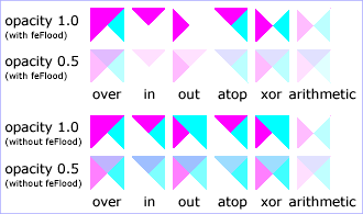
This filter performs the combination of the two input images
pixel-wise in image space using one of the Porter-Duff [PORTERDUFF] compositing operations:
over, in, atop, out, xor [SVG-COMPOSITING]. Additionally, a
component-wise arithmetic operation (with the result clamped
between [0..1]) can be applied.
The arithmetic operation is useful for combining the
output from the ‘feDiffuseLighting’ and ‘feSpecularLighting’ filters with texture
data. It is also useful for implementing dissolve. If the
arithmetic operation is chosen, each result pixel is computed
using the following formula:
result = k1*i1*i2 + k2*i1 + k3*i2 + k4
where:
-
i1 and i2 indicate the corresponding
pixel channel values of the input image, which map to ‘in’ and ‘in2’
respectively
-
k1, k2, k3 and k4 indicate the values
of the attributes with the same name
For this filter primitive, the extent of the resulting image might
grow as described in the section that describes the filter primitive subregion.
Attribute definitions:
- operator
= "over | in | out | atop | xor | arithmetic"
- The compositing operation that is to be performed. All of the
operator types except arithmetic match the corresponding operation
as described in [PORTERDUFF]. The
arithmetic operator is described
above. The lacuna
value for ‘
operator’ is over.
Animatable: yes.
- k1 = "<number>"
- Only applicable if operator="arithmetic".
The lacuna
value for ‘k1’
is 0.
Animatable: yes.
- k2 = "<number>"
- Only applicable if operator="arithmetic".
The lacuna
value for ‘k2’
is 0.
Animatable: yes.
- k3 = "<number>"
- Only applicable if operator="arithmetic".
The lacuna
value for ‘k3’
is 0.
Animatable: yes.
- k4 = "<number>"
- Only applicable if operator="arithmetic".
The lacuna
value for ‘k4’
is 0.
Animatable: yes.
- in2 =
"(see in attribute)"
- The second input image to the compositing operation. This
attribute can take on the same values as the in attribute.
Animatable: yes.
<?xml version="1.0"?>
<!DOCTYPE svg PUBLIC "-//W3C//DTD SVG 1.1//EN"
"http://www.w3.org/Graphics/SVG/1.1/DTD/svg11.dtd">
<svg width="330" height="195" viewBox="0 0 1100 650" version="1.1"
xmlns="http://www.w3.org/2000/svg" xmlns:xlink="http://www.w3.org/1999/xlink">
<title>Example feComposite - Examples of feComposite operations</title>
<desc>Four rows of six pairs of overlapping triangles depicting
the six different feComposite operators under different
opacity values and different clearing of the background.</desc>
<defs>
<desc>Define two sets of six filters for each of the six compositing operators.
The first set wipes out the background image by flooding with opaque white.
The second set does not wipe out the background, with the result
that the background sometimes shines through and is other cases
is blended into itself (i.e., "double-counting").</desc>
<filter id="overFlood" filterUnits="objectBoundingBox" x="-5%" y="-5%" width="110%" height="110%">
<feFlood flood-color="#ffffff" flood-opacity="1" result="flood"/>
<feComposite in="SourceGraphic" in2="BackgroundImage" operator="over" result="comp"/>
<feMerge> <feMergeNode in="flood"/> <feMergeNode in="comp"/> </feMerge>
</filter>
<filter id="inFlood" filterUnits="objectBoundingBox" x="-5%" y="-5%" width="110%" height="110%">
<feFlood flood-color="#ffffff" flood-opacity="1" result="flood"/>
<feComposite in="SourceGraphic" in2="BackgroundImage" operator="in" result="comp"/>
<feMerge> <feMergeNode in="flood"/> <feMergeNode in="comp"/> </feMerge>
</filter>
<filter id="outFlood" filterUnits="objectBoundingBox" x="-5%" y="-5%" width="110%" height="110%">
<feFlood flood-color="#ffffff" flood-opacity="1" result="flood"/>
<feComposite in="SourceGraphic" in2="BackgroundImage" operator="out" result="comp"/>
<feMerge> <feMergeNode in="flood"/> <feMergeNode in="comp"/> </feMerge>
</filter>
<filter id="atopFlood" filterUnits="objectBoundingBox" x="-5%" y="-5%" width="110%" height="110%">
<feFlood flood-color="#ffffff" flood-opacity="1" result="flood"/>
<feComposite in="SourceGraphic" in2="BackgroundImage" operator="atop" result="comp"/>
<feMerge> <feMergeNode in="flood"/> <feMergeNode in="comp"/> </feMerge>
</filter>
<filter id="xorFlood" filterUnits="objectBoundingBox" x="-5%" y="-5%" width="110%" height="110%">
<feFlood flood-color="#ffffff" flood-opacity="1" result="flood"/>
<feComposite in="SourceGraphic" in2="BackgroundImage" operator="xor" result="comp"/>
<feMerge> <feMergeNode in="flood"/> <feMergeNode in="comp"/> </feMerge>
</filter>
<filter id="arithmeticFlood" filterUnits="objectBoundingBox"
x="-5%" y="-5%" width="110%" height="110%">
<feFlood flood-color="#ffffff" flood-opacity="1" result="flood"/>
<feComposite in="SourceGraphic" in2="BackgroundImage" result="comp"
operator="arithmetic" k1=".5" k2=".5" k3=".5" k4=".5"/>
<feMerge> <feMergeNode in="flood"/> <feMergeNode in="comp"/> </feMerge>
</filter>
<filter id="overNoFlood" filterUnits="objectBoundingBox" x="-5%" y="-5%" width="110%" height="110%">
<feComposite in="SourceGraphic" in2="BackgroundImage" operator="over" result="comp"/>
</filter>
<filter id="inNoFlood" filterUnits="objectBoundingBox" x="-5%" y="-5%" width="110%" height="110%">
<feComposite in="SourceGraphic" in2="BackgroundImage" operator="in" result="comp"/>
</filter>
<filter id="outNoFlood" filterUnits="objectBoundingBox" x="-5%" y="-5%" width="110%" height="110%">
<feComposite in="SourceGraphic" in2="BackgroundImage" operator="out" result="comp"/>
</filter>
<filter id="atopNoFlood" filterUnits="objectBoundingBox" x="-5%" y="-5%" width="110%" height="110%">
<feComposite in="SourceGraphic" in2="BackgroundImage" operator="atop" result="comp"/>
</filter>
<filter id="xorNoFlood" filterUnits="objectBoundingBox" x="-5%" y="-5%" width="110%" height="110%">
<feComposite in="SourceGraphic" in2="BackgroundImage" operator="xor" result="comp"/>
</filter>
<filter id="arithmeticNoFlood" filterUnits="objectBoundingBox"
x="-5%" y="-5%" width="110%" height="110%">
<feComposite in="SourceGraphic" in2="BackgroundImage" result="comp"
operator="arithmetic" k1=".5" k2=".5" k3=".5" k4=".5"/>
</filter>
<path id="Blue100" d="M 0 0 L 100 0 L 100 100 z" fill="#00ffff" />
<path id="Red100" d="M 0 0 L 0 100 L 100 0 z" fill="#ff00ff" />
<path id="Blue50" d="M 0 125 L 100 125 L 100 225 z" fill="#00ffff" fill-opacity=".5" />
<path id="Red50" d="M 0 125 L 0 225 L 100 125 z" fill="#ff00ff" fill-opacity=".5" />
<g id="TwoBlueTriangles">
<use xlink:href="#Blue100"/>
<use xlink:href="#Blue50"/>
</g>
<g id="BlueTriangles">
<use transform="translate(275,25)" xlink:href="#TwoBlueTriangles"/>
<use transform="translate(400,25)" xlink:href="#TwoBlueTriangles"/>
<use transform="translate(525,25)" xlink:href="#TwoBlueTriangles"/>
<use transform="translate(650,25)" xlink:href="#TwoBlueTriangles"/>
<use transform="translate(775,25)" xlink:href="#TwoBlueTriangles"/>
<use transform="translate(900,25)" xlink:href="#TwoBlueTriangles"/>
</g>
</defs>
<rect fill="none" stroke="blue" x="1" y="1" width="1098" height="648"/>
<g font-family="Verdana" font-size="40" shape-rendering="crispEdges">
<desc>Render the examples using the filters that draw on top of
an opaque white surface, thus obliterating the background.</desc>
<g enable-background="new">
<text x="15" y="75">opacity 1.0</text>
<text x="15" y="115" font-size="27">(with feFlood)</text>
<text x="15" y="200">opacity 0.5</text>
<text x="15" y="240" font-size="27">(with feFlood)</text>
<use xlink:href="#BlueTriangles"/>
<g transform="translate(275,25)">
<use xlink:href="#Red100" filter="url(#overFlood)" />
<use xlink:href="#Red50" filter="url(#overFlood)" />
<text x="5" y="275">over</text>
</g>
<g transform="translate(400,25)">
<use xlink:href="#Red100" filter="url(#inFlood)" />
<use xlink:href="#Red50" filter="url(#inFlood)" />
<text x="35" y="275">in</text>
</g>
<g transform="translate(525,25)">
<use xlink:href="#Red100" filter="url(#outFlood)" />
<use xlink:href="#Red50" filter="url(#outFlood)" />
<text x="15" y="275">out</text>
</g>
<g transform="translate(650,25)">
<use xlink:href="#Red100" filter="url(#atopFlood)" />
<use xlink:href="#Red50" filter="url(#atopFlood)" />
<text x="10" y="275">atop</text>
</g>
<g transform="translate(775,25)">
<use xlink:href="#Red100" filter="url(#xorFlood)" />
<use xlink:href="#Red50" filter="url(#xorFlood)" />
<text x="15" y="275">xor</text>
</g>
<g transform="translate(900,25)">
<use xlink:href="#Red100" filter="url(#arithmeticFlood)" />
<use xlink:href="#Red50" filter="url(#arithmeticFlood)" />
<text x="-25" y="275">arithmetic</text>
</g>
</g>
<g transform="translate(0,325)" enable-background="new">
<desc>Render the examples using the filters that do not obliterate
the background, thus sometimes causing the background to continue
to appear in some cases, and in other cases the background
image blends into itself ("double-counting").</desc>
<text x="15" y="75">opacity 1.0</text>
<text x="15" y="115" font-size="27">(without feFlood)</text>
<text x="15" y="200">opacity 0.5</text>
<text x="15" y="240" font-size="27">(without feFlood)</text>
<use xlink:href="#BlueTriangles"/>
<g transform="translate(275,25)">
<use xlink:href="#Red100" filter="url(#overNoFlood)" />
<use xlink:href="#Red50" filter="url(#overNoFlood)" />
<text x="5" y="275">over</text>
</g>
<g transform="translate(400,25)">
<use xlink:href="#Red100" filter="url(#inNoFlood)" />
<use xlink:href="#Red50" filter="url(#inNoFlood)" />
<text x="35" y="275">in</text>
</g>
<g transform="translate(525,25)">
<use xlink:href="#Red100" filter="url(#outNoFlood)" />
<use xlink:href="#Red50" filter="url(#outNoFlood)" />
<text x="15" y="275">out</text>
</g>
<g transform="translate(650,25)">
<use xlink:href="#Red100" filter="url(#atopNoFlood)" />
<use xlink:href="#Red50" filter="url(#atopNoFlood)" />
<text x="10" y="275">atop</text>
</g>
<g transform="translate(775,25)">
<use xlink:href="#Red100" filter="url(#xorNoFlood)" />
<use xlink:href="#Red50" filter="url(#xorNoFlood)" />
<text x="15" y="275">xor</text>
</g>
<g transform="translate(900,25)">
<use xlink:href="#Red100" filter="url(#arithmeticNoFlood)" />
<use xlink:href="#Red50" filter="url(#arithmeticNoFlood)" />
<text x="-25" y="275">arithmetic</text>
</g>
</g>
</g>
</svg>
Example
|
View this
example as SVG (SVG-enabled browsers only)
| Name:
| feConvolveMatrix
|
| Categories:
| Filter primitive
element
|
| Content model:
| Any number of the following elements, in any order:
|
| Attributes:
|
- core
attributes — ‘id’, ‘xml:base’, ‘xml:lang’, ‘xml:space’
- presentation
attributes — ‘alignment-baseline’, ‘baseline-shift’, ‘clip’, ‘clip-path’, ‘clip-rule’, ‘color’, ‘color-interpolation’, ‘color-interpolation-filters’, ‘color-profile’, ‘color-rendering’, ‘cursor’, ‘direction’, ‘display’, ‘dominant-baseline’, ‘enable-background’, ‘fill’, ‘fill-opacity’, ‘fill-rule’, ‘filter’, ‘flood-color’, ‘flood-opacity’, ‘font’, ‘font-family’, ‘font-size’, ‘font-size-adjust’, ‘font-stretch’, ‘font-style’, ‘font-variant’, ‘font-weight’, ‘glyph-orientation-horizontal’, ‘glyph-orientation-vertical’, ‘image-rendering’, ‘kerning’, ‘letter-spacing’, ‘lighting-color’, ‘marker’, ‘marker-end’, ‘marker-mid’, ‘marker-start’, ‘mask’, ‘opacity’, ‘overflow’, ‘pointer-events’, ‘shape-rendering’, ‘stop-color’, ‘stop-opacity’, ‘stroke’, ‘stroke-dasharray’, ‘stroke-dashoffset’, ‘stroke-linecap’, ‘stroke-linejoin’, ‘stroke-miterlimit’, ‘stroke-opacity’, ‘stroke-width’, ‘text-anchor’, ‘text-decoration’, ‘text-rendering’, ‘unicode-bidi’, ‘visibility’, ‘word-spacing’, ‘writing-mode’
- filter primitive
attributes — ‘x’, ‘y’, ‘width’, ‘height’, ‘result’
- ‘class’
- ‘style’
- ‘in’
- ‘order’
- ‘kernelMatrix’
- ‘divisor’
- ‘bias’
- ‘targetX’
- ‘targetY’
- ‘edgeMode’
- ‘kernelUnitLength’
- ‘preserveAlpha’
|
| DOM Interfaces:
| SVGFEConvolveMatrixElement
|
feConvolveMatrix applies a matrix convolution filter effect. A
convolution combines pixels in the input image with neighboring pixels
to produce a resulting image. A wide variety of imaging operations can
be achieved through convolutions, including blurring, edge detection,
sharpening, embossing and beveling.
A matrix convolution is based on an n-by-m matrix (the convolution
kernel) which describes how a given pixel value in the input image is
combined with its neighboring pixel values to produce a resulting
pixel value. Each result pixel is determined by applying the kernel
matrix to the corresponding source pixel and its neighboring pixels.
The basic convolution formula which is applied to each color value for
a given pixel is:
COLORX,Y = (
SUM I=0 to [‘orderY’-1] {
SUM J=0 to [‘orderX’-1] {
SOURCE X-‘targetX’+J, Y-‘targetY’+I * ‘kernelMatrix’‘orderX’-J-1, ‘orderY’-I-1
}
}
) / ‘divisor’ + ‘bias’ * ALPHAX,Y
ED: Consider making this into mathml
where "orderX" and "orderY" represent the X and Y values for the ‘order’ attribute, "targetX" represents the
value of the ‘targetX’ attribute, "targetY" represents
the value of the ‘targetY’ attribute, "kernelMatrix"
represents the value of the ‘kernelMatrix’ attribute, "divisor"
represents the value of the ‘divisor’ attribute, and "bias" represents
the value of the ‘bias’ attribute.
Note in the above formulas that the values in the kernel matrix are
applied such that the kernel matrix is rotated 180 degrees relative to
the source and destination images in order to match convolution theory
as described in many computer graphics textbooks.
To illustrate, suppose you have a input image which is 5 pixels by
5 pixels, whose color values for one of the color channels are as
follows:
0 20 40 235 235
100 120 140 235 235
200 220 240 235 235
225 225 255 255 255
225 225 255 255 255
ED: Consider making this into mathml
and you define a 3-by-3 convolution kernel as follows:
1
2
3


4
5

6
7 8 9
ED: Consider making this into mathml
Let's focus on the color value at the second row and second column
of the image (source pixel value is 120). Assuming the simplest case
(where the input image's pixel grid aligns perfectly with the kernel's
pixel grid) and assuming default values for attributes ‘divisor’, ‘targetX’ and ‘targetY’, then resulting color value will
be:
(9* 0 + 8* 20 + 7* 40 +
6*100 + 5*120 + 4*140 +
3*200 + 2*220 + 1*240) / (9+8+7+6+5+4+3+2+1)
ED: Consider making this into mathml
Because they operate on pixels, matrix convolutions are inherently
resolution-dependent. To make ‘feConvolveMatrix’ produce
resolution-independent results, an explicit value should be provided
for either the ‘filterRes’ attribute on the ‘filter’ element and/or attribute ‘kernelUnitLength’.
‘kernelUnitLength’, in combination with the
other attributes, defines an implicit pixel grid in the filter effects
coordinate system (i.e., the coordinate system established by the ‘primitiveUnits’ attribute). If the pixel
grid established by ‘kernelUnitLength’ is not scaled to match
the pixel grid established by attribute ‘filterRes’ (implicitly or explicitly),
then the input image will be temporarily rescaled to match its pixels
with ‘kernelUnitLength’. The convolution happens
on the resampled image. After applying the convolution, the image is
resampled back to the original resolution.
When the image must be resampled to match the coordinate system
defined by ‘kernelUnitLength’ prior to convolution, or
resampled to match the device coordinate system after convolution, it
is recommended that high quality viewers make use of appropriate
interpolation techniques, for example bilinear or bicubic. Depending
on the speed of the available interpolents, this choice may be
affected by the ‘image-rendering’ property setting. Note
that implementations might choose approaches that minimize or
eliminate resampling when not necessary to produce proper results,
such as when the document is zoomed out such that ‘kernelUnitLength’ is considerably smaller
than a device pixel.
Attribute definitions:
- order = "<number-optional-number>"
- Indicates the number of cells in each dimension for ‘
kernelMatrix’. The values provided must
be <integer>
s greater than zero. Values that are not integers will be truncated,
i.e. rounded to the closest integer value towards zero. The first
number, <orderX>, indicates the number of columns in the
matrix. The second number, <orderY>, indicates the number of
rows in the matrix. If <orderY> is not provided, it defaults
to <orderX>.
It is recommended that only small values (e.g., 3) be used; higher
values may result in very high CPU overhead and usually do not
produce results that justify the impact on performance.
The lacuna
value for ‘order’ is 3.
Animatable: yes.
- kernelMatrix = "<list of
numbers>"
- The list of <number>
s that make up the kernel matrix for the convolution. Values are
separated by space characters and/or a comma. The number of entries
in the list must equal <orderX> times <orderY>.
Animatable: yes.
- divisor = "<number>"
- After applying the kernelMatrix to
the input image to yield a number, that number is divided by ‘
divisor’ to yield the final destination
color value. A divisor that is the sum of all the matrix values
tends to have an evening effect on the overall color intensity of
the result. If the specified divisor is zero then the default value
will be used instead. The lacuna
value is the sum of all values in kernelMatrix, with the
exception that if the sum is zero, then the divisor is set to 1.
Animatable: yes.
- bias = "<number>"
- After applying the kernelMatrix to
the input image to yield a number and applying the ‘
divisor’, the ‘bias’ attribute is added to each
component. One application of ‘bias’ is when it is desirable to have
.5 gray value be the zero response of
the filter. The bias property shifts the range of the filter. This
allows representation of values that would otherwise be clamped to 0
or 1.
The lacuna
value for ‘bias’ is 0.
Animatable: yes.
- targetX = "<integer>"
- Determines the positioning in X of the convolution matrix
relative to a given target pixel in the input image. The leftmost
column of the matrix is column number zero. The value must be such
that: 0 <= targetX < orderX. By default, the convolution
matrix is centered in X over each pixel of the input image (i.e.,
targetX = floor ( orderX / 2 )).
Animatable: yes.
- targetY = "<integer>"
- Determines the positioning in Y of the convolution matrix
relative to a given target pixel in the input image. The topmost row
of the matrix is row number zero. The value must be such that: 0
<= targetY < orderY. By default, the convolution matrix is
centered in Y over each pixel of the input image (i.e., targetY =
floor ( orderY / 2 )).
Animatable: yes.
- edgeMode = "duplicate |
wrap | none"
-
Determines how to extend the input image as necessary with color
values so that the matrix operations can be applied when the kernel
is positioned at or near the edge of the input image.
"duplicate" indicates that the input image is extended along each
of its borders as necessary by duplicating the color values at the
given edge of the input image.
Original N-by-M image, where m=M-1 and n=N-1:
11 12 ... 1m 1M
21 22 ... 2m 2M
.. .. ... .. ..
n1 n2 ... nm nM
N1 N2 ... Nm NM
Extended by two pixels using "duplicate":
11 11 11 12 ... 1m 1M 1M 1M
11 11 11 12 ... 1m 1M 1M 1M
11 11 11 12 ... 1m 1M 1M 1M
21 21 21 22 ... 2m 2M 2M 2M
.. .. .. .. ... .. .. .. ..
n1 n1 n1 n2 ... nm nM nM nM
N1 N1 N1 N2 ... Nm NM NM NM
N1 N1 N1 N2 ... Nm NM NM NM
N1 N1 N1 N2 ... Nm NM NM NM
ED: Consider making this into mathml
"wrap" indicates that the input image is extended by taking the
color values from the opposite edge of the image.
Extended by two pixels using "wrap":
nm nM n1 n2 ... nm nM n1 n2
Nm NM N1 N2 ... Nm NM N1 N2
1m 1M 11 12 ... 1m 1M 11 12
2m 2M 21 22 ... 2m 2M 21 22
.. .. .. .. ... .. .. .. ..
nm nM n1 n2 ... nm nM n1 n2
Nm NM N1 N2 ... Nm NM N1 N2
1m 1M 11 12 ... 1m 1M 11 12
2m 2M 21 22 ... 2m 2M 21 22
ED: Consider making this into mathml
The value none indicates that the
input image is extended with pixel values of zero for R, G, B and
A.
The lacuna
value for ‘edgeMode’ is duplicate.
Animatable: yes.
- kernelUnitLength = "<number-optional-number>"
- The first number is the <dx> value. The second number is
the <dy> value. If the <dy> value is not specified, it
defaults to the same value as <dx>. Indicates the intended
distance in current filter units (i.e., units as determined by the
value of attribute ‘
primitiveUnits’) between successive
columns and rows, respectively, in the ‘kernelMatrix’. By specifying value(s)
for ‘kernelUnitLength’, the kernel becomes
defined in a scalable, abstract coordinate system. If ‘kernelUnitLength’ is not specified, the
default value is one pixel in the offscreen bitmap, which is a
pixel-based coordinate system, and thus potentially not scalable.
For some level of consistency across display media and user agents,
it is necessary that a value be provided for at least one of ‘filterRes’ and ‘kernelUnitLength’. In some
implementations, the most consistent results and the fastest
performance will be achieved if the pixel grid of the temporary
offscreen images aligns with the pixel grid of the kernel.
If a negative or zero value is specified the default value will be
used instead.
Animatable: yes.
- preserveAlpha = "false |
true"
- A value of false indicates that the
convolution will apply to all channels, including the alpha channel.
In this case the
ALPHAX,Y of the convolution formula for a
given pixel is:
ALPHAX,Y = (
SUM I=0 to [‘orderY’-1] {
SUM J=0 to [‘orderX’-1] {
SOURCE X-‘targetX’+J, Y-‘targetY’+I * ‘kernelMatrix’‘orderX’-J-1, ‘orderY’-I-1
}
}
) / ‘divisor’ + ‘bias’
A value of true indicates that the
convolution will only apply to the color channels. In this case, the
filter will temporarily unpremultiply the color component values,
apply the kernel, and then re-premultiply at the end. In this case
the ALPHAX,Y of the convolution formula for a
given pixel is:
ALPHAX,Y = SOURCEX,Y
The lacuna
value for ‘preserveAlpha’ is false.
Animatable: yes.
| Name:
| feDiffuseLighting
|
| Categories:
| Filter primitive
element
|
| Content model:
| Any number of descriptive
elements and exactly one light source element, in any
order.
|
| Attributes:
|
- core
attributes — ‘id’, ‘xml:base’, ‘xml:lang’, ‘xml:space’
- presentation
attributes — ‘alignment-baseline’, ‘baseline-shift’, ‘clip’, ‘clip-path’, ‘clip-rule’, ‘color’, ‘color-interpolation’, ‘color-interpolation-filters’, ‘color-profile’, ‘color-rendering’, ‘cursor’, ‘direction’, ‘display’, ‘dominant-baseline’, ‘enable-background’, ‘fill’, ‘fill-opacity’, ‘fill-rule’, ‘filter’, ‘flood-color’, ‘flood-opacity’, ‘font’, ‘font-family’, ‘font-size’, ‘font-size-adjust’, ‘font-stretch’, ‘font-style’, ‘font-variant’, ‘font-weight’, ‘glyph-orientation-horizontal’, ‘glyph-orientation-vertical’, ‘image-rendering’, ‘kerning’, ‘letter-spacing’, ‘lighting-color’, ‘marker’, ‘marker-end’, ‘marker-mid’, ‘marker-start’, ‘mask’, ‘opacity’, ‘overflow’, ‘pointer-events’, ‘shape-rendering’, ‘stop-color’, ‘stop-opacity’, ‘stroke’, ‘stroke-dasharray’, ‘stroke-dashoffset’, ‘stroke-linecap’, ‘stroke-linejoin’, ‘stroke-miterlimit’, ‘stroke-opacity’, ‘stroke-width’, ‘text-anchor’, ‘text-decoration’, ‘text-rendering’, ‘unicode-bidi’, ‘visibility’, ‘word-spacing’, ‘writing-mode’
- filter primitive
attributes — ‘x’, ‘y’, ‘width’, ‘height’, ‘result’
- ‘class’
- ‘style’
- ‘in’
- ‘surfaceScale’
- ‘diffuseConstant’
- ‘kernelUnitLength’
|
| DOM Interfaces:
| SVGFEDiffuseLightingElement
|
This filter primitive lights an image using the alpha channel as a
bump map. The resulting image is an RGBA opaque image based on the
light color with alpha = 1.0 everywhere. The lighting calculation
follows the standard diffuse component of the Phong lighting model.
The resulting image depends on the light color, light position and
surface geometry of the input bump map.
The light map produced by this filter primitive can be combined
with a texture image using the multiply term of the
arithmetic ‘feComposite’ compositing method. Multiple
light sources can be simulated by adding several of these light maps
together before applying it to the texture image.
The formulas below make use of 3x3 filters. Because they operate on
pixels, such filters are inherently resolution-dependent. To make ‘feDiffuseLighting’ produce
resolution-independent results, an explicit value should be provided
for either the ‘filterRes’ attribute on the ‘filter’ element and/or attribute ‘kernelUnitLength’.
‘kernelUnitLength’, in combination with the
other attributes, defines an implicit pixel grid in the filter effects
coordinate system (i.e., the coordinate system established by the ‘primitiveUnits’ attribute). If the pixel
grid established by ‘kernelUnitLength’ is not scaled to match
the pixel grid established by attribute ‘filterRes’ (implicitly or explicitly),
then the input image will be temporarily rescaled to match its pixels
with ‘kernelUnitLength’. The 3x3 filters are
applied to the resampled image. After applying the filter, the image
is resampled back to its original resolution.
When the image must be
resampled, it is recommended that high quality viewers make use of
appropriate interpolation techniques, for example bilinear or
bicubic. Depending on the speed of the available interpolents,
this choice may be affected by the ‘image-rendering’ property setting. Note
that implementations might choose approaches that minimize or
eliminate resampling when not necessary to produce proper results,
such as when the document is zoomed out such that ‘kernelUnitLength’ is considerably smaller
than a device pixel.
For the formulas that follow, the
Norm(Ax,Ay,Az) function
is defined as:
ED: Consider making the following in mathml
Norm(Ax,Ay,Az)
= sqrt(Ax^2+Ay^2+Az^2)
The resulting RGBA image is computed as follows:
Dr = kd * N.L *
Lr
Dg = kd * N.L * Lg
Db = kd * N.L * Lb
Da = 1.0
where
- kd = diffuse lighting constant
N = surface normal unit vector, a function of x and y
L = unit vector pointing from surface to light, a function of x and y
in the point and spot light cases
Lr,Lg,Lb = RGB components of light,
a function of x and y in the spot light case
N is a function of x and y and depends on the surface gradient as
follows:
The surface described by the input alpha image I(x,y) is:
Z (x,y) = surfaceScale * I(x,y)
Surface normal is calculated using the
Sobel gradient 3x3 filter. Different filter kernels are used depending
on whether the given pixel is on the interior or an edge. For each
case, the formula is:
Nx (x,y) = - surfaceScale *
FACTORx *
(Kx(0,0)*I(x-dx,y-dy) +
Kx(1,0)*I(x,y-dy) + Kx(2,0)*I(x+dx,y-dy) +
Kx(0,1)*I(x-dx,y) +
Kx(1,1)*I(x,y) +
Kx(2,1)*I(x+dx,y) +
Kx(0,2)*I(x-dx,y+dy) +
Kx(1,2)*I(x,y+dy) + Kx(2,2)*I(x+dx,y+dy))
Ny (x,y) = - surfaceScale * FACTORy *
(Ky(0,0)*I(x-dx,y-dy) +
Ky(1,0)*I(x,y-dy) + Ky(2,0)*I(x+dx,y-dy) +
Ky(0,1)*I(x-dx,y) +
Ky(1,1)*I(x,y) +
Ky(2,1)*I(x+dx,y) +
Ky(0,2)*I(x-dx,y+dy) +
Ky(1,2)*I(x,y+dy) + Ky(2,2)*I(x+dx,y+dy))
Nz (x,y) = 1.0
N = (Nx, Ny, Nz) /
Norm((Nx,Ny,Nz))
In these formulas, the dx and dy values
(e.g., I(x-dx,y-dy)), represent deltas relative to a
given (x,y) position for the purpose of estimating the
slope of the surface at that point. These deltas are determined by the
value (explicit or implicit) of attribute ‘kernelUnitLength’.
|
Top/left corner:
FACTORx=2/(3*dx)
Kx =
| 0 0 0 |
| 0 -2 2 |
| 0 -1 1 |
FACTORy=2/(3*dy)
Ky =
| 0 0 0 |
| 0 -2 -1 |
| 0 2 1 |
|
Top row:
FACTORx=1/(3*dx)
Kx =
| 0 0 0 |
| -2 0 2 |
| -1 0 1 |
FACTORy=1/(2*dy)
Ky =
| 0 0 0 |
| -1 -2 -1 |
| 1 2 1 |
|
Top/right corner:
FACTORx=2/(3*dx)
Kx =
| 0 0 0 |
| -2 2 0 |
| -1 1 0 |
FACTORy=2/(3*dy)
Ky =
| 0 0 0 |
| -1 -2 0 |
| 1 2 0 |
|
|
Left column:
FACTORx=1/(2*dx)
Kx =
| 0 -1 1 |
| 0 -2 2 |
| 0 -1 1 |
FACTORy=1/(3*dy)
Ky =
| 0 -2 -1 |
| 0 0 0 |
| 0 2 1 |
|
Interior pixels:
FACTORx=1/(4*dx)
Kx =
| -1 0 1 |
| -2 0 2 |
| -1 0 1 |
FACTORy=1/(4*dy)
Ky =
| -1 -2 -1 |
| 0 0 0 |
| 1 2 1 |
|
Right column:
FACTORx=1/(2*dx)
Kx =
| -1 1 0|
| -2 2 0|
| -1 1 0|
FACTORy=1/(3*dy)
Ky =
| -1 -2 0 |
| 0 0 0 |
| 1 2 0 |
|
|
Bottom/left corner:
FACTORx=2/(3*dx)
Kx =
| 0 -1 1 |
| 0 -2 2 |
| 0 0 0 |
FACTORy=2/(3*dy)
Ky =
| 0 -2 -1 |
| 0 2 1 |
| 0 0 0 |
|
Bottom row:
FACTORx=1/(3*dx)
Kx =
| -1 0 1 |
| -2 0 2 |
| 0 0 0 |
FACTORy=1/(2*dy)
Ky =
| -1 -2 -1 |
| 1 2 1 |
| 0 0 0 |
|
Bottom/right corner:
FACTORx=2/(3*dx)
Kx =
| -1 1 0 |
| -2 2 0 |
| 0 0 0 |
FACTORy=2/(3*dy)
Ky =
| -1 -2 0 |
| 1 2 0 |
| 0 0 0 |
|
L, the unit vector from the image sample to the light, is
calculated as follows:
For Infinite light sources it is constant:
Lx = cos(azimuth)*cos(elevation)
Ly = sin(azimuth)*cos(elevation)
Lz = sin(elevation)
For Point and spot lights it is a function of position:
Lx = Lightx - x
Ly = Lighty - y
Lz = Lightz - Z(x,y)
L = (Lx, Ly, Lz) /
Norm(Lx, Ly, Lz)
where Lightx, Lighty, and Lightz
are the input light position.
Lr,Lg,Lb, the light color vector,
is a function of position in the spot light case only:
Lr =
Lightr*pow((-L.S),specularExponent)
Lg = Lightg*pow((-L.S),specularExponent)
Lb = Lightb*pow((-L.S),specularExponent)
where S is the unit vector pointing from the light to the point
(pointsAtX, pointsAtY, pointsAtZ) in the x-y plane:
Sx = pointsAtX -
Lightx
Sy = pointsAtY - Lighty
Sz = pointsAtZ - Lightz
S = (Sx, Sy, Sz) /
Norm(Sx, Sy, Sz)
If L.S is positive, no light is present. (Lr =
Lg = Lb = 0). If ‘limitingConeAngle’ is specified, -L.S <
cos(limitingConeAngle) also indicates that no light is present.
Attribute definitions:
- surfaceScale = "<number>"
- height of surface when Ain = 1.
If the attribute is not specified, then the effect is as if a value
of 1 were specified.
Animatable: yes.
- diffuseConstant = "<number>"
- kd in Phong lighting model. In SVG, this can be any non-negative
number.
If the attribute is not specified, then the effect is as if a value
of 1 were specified.
Animatable: yes.
- kernelUnitLength = "<number-optional-number>"
- The first number is the <dx> value. The second number is
the <dy> value. If the <dy> value is not specified, it
defaults to the same value as <dx>. Indicates the intended
distance in current filter units (i.e., units as determined by the
value of attribute ‘
primitiveUnits’) for dx and
dy, respectively, in the surface normal calculation
formulas. By specifying value(s) for kernelUnitLength, the kernel becomes defined
in a scalable, abstract coordinate system. If kernelUnitLength is not specified, the
dx and dy values should represent very
small deltas relative to a given (x,y) position, which
might be implemented in some cases as one pixel in the intermediate
image offscreen bitmap, which is a pixel-based coordinate system,
and thus potentially not scalable. For some level of consistency
across display media and user agents, it is necessary that a value
be provided for at least one of ‘filterRes’ and kernelUnitLength. Discussion of intermediate
images are in the Introduction and in
the description of attribute ‘filterRes’.
If a negative or zero value is specified the default value will be
used instead.
Animatable: yes.
The light source is defined by one of the child elements ‘feDistantLight’, ‘fePointLight’ or ‘feSpotLight’. The light color is specified
by property ‘lighting-color’.
| Name:
| feDisplacementMap
|
| Categories:
| Filter primitive
element
|
| Content model:
| Any number of the following elements, in any order:
|
| Attributes:
|
- core
attributes — ‘id’, ‘xml:base’, ‘xml:lang’, ‘xml:space’
- presentation
attributes — ‘alignment-baseline’, ‘baseline-shift’, ‘clip’, ‘clip-path’, ‘clip-rule’, ‘color’, ‘color-interpolation’, ‘color-interpolation-filters’, ‘color-profile’, ‘color-rendering’, ‘cursor’, ‘direction’, ‘display’, ‘dominant-baseline’, ‘enable-background’, ‘fill’, ‘fill-opacity’, ‘fill-rule’, ‘filter’, ‘flood-color’, ‘flood-opacity’, ‘font’, ‘font-family’, ‘font-size’, ‘font-size-adjust’, ‘font-stretch’, ‘font-style’, ‘font-variant’, ‘font-weight’, ‘glyph-orientation-horizontal’, ‘glyph-orientation-vertical’, ‘image-rendering’, ‘kerning’, ‘letter-spacing’, ‘lighting-color’, ‘marker’, ‘marker-end’, ‘marker-mid’, ‘marker-start’, ‘mask’, ‘opacity’, ‘overflow’, ‘pointer-events’, ‘shape-rendering’, ‘stop-color’, ‘stop-opacity’, ‘stroke’, ‘stroke-dasharray’, ‘stroke-dashoffset’, ‘stroke-linecap’, ‘stroke-linejoin’, ‘stroke-miterlimit’, ‘stroke-opacity’, ‘stroke-width’, ‘text-anchor’, ‘text-decoration’, ‘text-rendering’, ‘unicode-bidi’, ‘visibility’, ‘word-spacing’, ‘writing-mode’
- filter primitive
attributes — ‘x’, ‘y’, ‘width’, ‘height’, ‘result’
- ‘class’
- ‘style’
- ‘in’
- ‘in2’
- ‘scale’
- ‘xChannelSelector’
- ‘yChannelSelector’
|
| DOM Interfaces:
| SVGFEDisplacementMapElement
|
This filter primitive uses the pixels values from the image from ‘in2’ to spatially displace the image from ‘in’. This is the transformation to be
performed:
P'(x,y) ← P( x + scale * (XC(x,y) - .5), y + scale * (YC(x,y) - .5))
where P(x,y) is the input image, ‘in’, and P'(x,y) is the destination.
XC(x,y) and YC(x,y) are the component values of the channel designated
by the ‘xChannelSelector’ and ‘yChannelSelector’. For example, to use the
R component of ‘in2’ to control displacement in x and the G
component of Image2 to control displacement in y, set ‘xChannelSelector’ to "R" and ‘yChannelSelector’ to "G".
The displacement map, ‘in2’, defines the inverse of the mapping
performed.
The input image in is to remain premultiplied for this filter
primitive. The calculations using the pixel values from ‘in2’ are performed using non-premultiplied
color values. If the image from ‘in2’ consists of premultiplied color values,
those values are automatically converted into non-premultiplied color
values before performing this operation.
This filter can have arbitrary non-localized effect on the input
which might require substantial buffering in the processing pipeline.
However with this formulation, any intermediate buffering needs can be
determined by ‘scale’ which represents the maximum range
of displacement in either x or y.
When applying this filter, the source pixel location will often lie
between several source pixels. In this case it is recommended that
high quality viewers apply an interpolent on the surrounding pixels,
for example bilinear or bicubic, rather than simply selecting the
nearest source pixel. Depending on the speed of the available
interpolents, this choice may be affected by the ‘image-rendering’ property setting.
The ‘color-interpolation-filters’ property only
applies to the ‘in2’ source image and does not apply to the ‘in’ source image. The ‘in’ source image must remain in its
current color space.
Attribute definitions:
- scale
= "<number>"
- Displacement scale factor. The amount is expressed in the
coordinate system established by attribute ‘
primitiveUnits’ on the ‘filter’ element.
When the value of this attribute is 0,
this operation has no effect on the source image.
The lacuna
value for ‘scale’ is 0.
Animatable: yes.
- xChannelSelector = "R | G | B | A"
- Indicates which channel from ‘
in2’ to use to displace the pixels in ‘in’ along the x-axis. The lacuna
value for ‘xChannelSelector’ is A.
Animatable: yes.
- yChannelSelector = "R | G | B | A"
- Indicates which channel from ‘
in2’ to use to displace the pixels in ‘in’ along the y-axis. The lacuna
value for ‘yChannelSelector’ is A.
Animatable: yes.
- in2 =
"(see ‘
in’ attribute)"
- The second input image, which is used to displace the pixels in
the image from attribute ‘
in’. This attribute can take on the same
values as the ‘in’ attribute.
Animatable: yes.
20. Filter primitive ‘feFlood’
| Name:
| feFlood
|
| Categories:
| Filter primitive
element
|
| Content model:
| Any number of the following elements, in any order:
|
| Attributes:
|
- core
attributes — ‘id’, ‘xml:base’, ‘xml:lang’, ‘xml:space’
- presentation
attributes — ‘alignment-baseline’, ‘baseline-shift’, ‘clip’, ‘clip-path’, ‘clip-rule’, ‘color’, ‘color-interpolation’, ‘color-interpolation-filters’, ‘color-profile’, ‘color-rendering’, ‘cursor’, ‘direction’, ‘display’, ‘dominant-baseline’, ‘enable-background’, ‘fill’, ‘fill-opacity’, ‘fill-rule’, ‘filter’, ‘flood-color’, ‘flood-opacity’, ‘font’, ‘font-family’, ‘font-size’, ‘font-size-adjust’, ‘font-stretch’, ‘font-style’, ‘font-variant’, ‘font-weight’, ‘glyph-orientation-horizontal’, ‘glyph-orientation-vertical’, ‘image-rendering’, ‘kerning’, ‘letter-spacing’, ‘lighting-color’, ‘marker’, ‘marker-end’, ‘marker-mid’, ‘marker-start’, ‘mask’, ‘opacity’, ‘overflow’, ‘pointer-events’, ‘shape-rendering’, ‘stop-color’, ‘stop-opacity’, ‘stroke’, ‘stroke-dasharray’, ‘stroke-dashoffset’, ‘stroke-linecap’, ‘stroke-linejoin’, ‘stroke-miterlimit’, ‘stroke-opacity’, ‘stroke-width’, ‘text-anchor’, ‘text-decoration’, ‘text-rendering’, ‘unicode-bidi’, ‘visibility’, ‘word-spacing’, ‘writing-mode’
- filter primitive
attributes — ‘x’, ‘y’, ‘width’, ‘height’, ‘result’
- ‘class’
- ‘style’
|
| DOM Interfaces:
| SVGFEFloodElement
|
This filter primitive creates a rectangle filled with the color and
opacity values from properties ‘flood-color’ and ‘flood-opacity’. The rectangle is as large
as the filter primitive
subregion established by the ‘feFlood’
element.
The ‘flood-color’ property indicates what color
to use to flood the current filter
primitive subregion. The keyword ‘currentColor’ and ICC colors can be specified in
the same manner as within a <paint> specification for the
‘fill’ and ‘stroke’ properties.
The ‘flood-opacity’ property defines the
opacity value to use across the entire filter primitive subregion.
| Name:
| flood-opacity
|
| Value:
| <number> | <percentage>
|
| Initial:
| 1
|
| Applies to:
| ‘feFlood’ and ‘feDropShadow’ elements
|
| Inherited:
| no
|
| Percentages:
| N/A
|
| Media:
| visual
|
| Animatable:
| yes
|
| Name:
| feGaussianBlur
|
| Categories:
| Filter primitive
element
|
| Content model:
| Any number of the following elements, in any order:
|
| Attributes:
|
- core
attributes — ‘id’, ‘xml:base’, ‘xml:lang’, ‘xml:space’
- presentation
attributes — ‘alignment-baseline’, ‘baseline-shift’, ‘clip’, ‘clip-path’, ‘clip-rule’, ‘color’, ‘color-interpolation’, ‘color-interpolation-filters’, ‘color-profile’, ‘color-rendering’, ‘cursor’, ‘direction’, ‘display’, ‘dominant-baseline’, ‘enable-background’, ‘fill’, ‘fill-opacity’, ‘fill-rule’, ‘filter’, ‘flood-color’, ‘flood-opacity’, ‘font’, ‘font-family’, ‘font-size’, ‘font-size-adjust’, ‘font-stretch’, ‘font-style’, ‘font-variant’, ‘font-weight’, ‘glyph-orientation-horizontal’, ‘glyph-orientation-vertical’, ‘image-rendering’, ‘kerning’, ‘letter-spacing’, ‘lighting-color’, ‘marker’, ‘marker-end’, ‘marker-mid’, ‘marker-start’, ‘mask’, ‘opacity’, ‘overflow’, ‘pointer-events’, ‘shape-rendering’, ‘stop-color’, ‘stop-opacity’, ‘stroke’, ‘stroke-dasharray’, ‘stroke-dashoffset’, ‘stroke-linecap’, ‘stroke-linejoin’, ‘stroke-miterlimit’, ‘stroke-opacity’, ‘stroke-width’, ‘text-anchor’, ‘text-decoration’, ‘text-rendering’, ‘unicode-bidi’, ‘visibility’, ‘word-spacing’, ‘writing-mode’
- filter primitive
attributes — ‘x’, ‘y’, ‘width’, ‘height’, ‘result’
- ‘class’
- ‘style’
- ‘in’
- ‘stdDeviation’
|
| DOM Interfaces:
| SVGFEGaussianBlurElement
|
This filter primitive performs a Gaussian blur on the input image.
The Gaussian blur kernel is an approximation of the normalized
convolution:
G(x,y) = H(x)I(y)
where
H(x) = exp(-x2/ (2s2)) /
sqrt(2* pi*s2)
and
I(x) = exp(-y2/ (2t2)) /
sqrt(2* pi*t2)
with ‘s’ being the standard
deviation in the x direction and ‘t’
being the standard deviation in the y direction, as specified by ‘stdDeviation’.
The value of ‘stdDeviation’ can be either one or two
numbers. If two numbers are provided, the first number represents a
standard deviation value along the x-axis of the current coordinate
system and the second value represents a standard deviation in Y. If
one number is provided, then that value is used for both X and Y.
Even if only one value is provided for ‘stdDeviation’, this can be implemented as
a separable convolution.
For larger values of ‘s’ (s >=
2.0), an approximation can be used: Three successive box-blurs build a
piece-wise quadratic convolution kernel, which approximates the
Gaussian kernel to within roughly 3%.
let d = floor(s * 3*sqrt(2*pi)/4 + 0.5)
... if d is odd, use three box-blurs of size ‘d’, centered on the output pixel.
... if d is even, two box-blurs of size ‘d’ (the first one centered on the pixel
boundary between the output pixel and the one to the left, the second
one centered on the pixel boundary between the output pixel and the
one to the right) and one box blur of size ‘d+1’ centered on the output pixel.
The approximation formula also applies correspondingly to ‘t’.
Frequently this operation will take place on alpha-only images,
such as that produced by the built-in input, SourceAlpha. The
implementation may notice this and optimize the single channel case.
If the input has infinite extent and is constant (e.g FillPaint where the
fill is a solid color), this operation has no effect. If the input has
infinite extent and the filter resultwhere the fill is a solid color)
is the input to an ‘feTile’,
the filter is evaluated with periodic boundary conditions.
By default, the subregion interacts as input and output
clipping and this sentence would be irrelevant. However, this changes
if the WG decides to allow a choice between input and output clipping.
What about other inputs with infinite extends? What is
the ‘periodic boundary condition’?
Attribute definitions:
- stdDeviation = "<number-optional-number>"
- The standard deviation for the blur operation. If two <number>
s are provided, the first number represents a standard deviation
value along the x-axis of the coordinate system established by
attribute ‘
primitiveUnits’ on the ‘filter’ element. The second value
represents a standard deviation in Y. If one number is provided,
then that value is used for both X and Y.
A value of zero disables the effect of the given filter primitive
(i.e., the result is the filter input image).
If ‘stdDeviation’ is 0 in only one of X or Y, then the effect is
that the blur is only applied in the direction that has a non-zero
value.
The lacuna
value for ‘stdDeviation’ is 0.
Animatable: yes.
The example at the start of this chapter
makes use of the ‘feGaussianBlur’ filter primitive to create
a drop shadow effect.
| Name:
| feUnsharpMask
|
| Categories:
| Filter primitive
element
|
| Content model:
| Any number of the following elements, in any order:
|
| Attributes:
|
- core
attributes — ‘id’, ‘xml:base’, ‘xml:lang’, ‘xml:space’
- presentation
attributes — ‘alignment-baseline’, ‘baseline-shift’, ‘clip’, ‘clip-path’, ‘clip-rule’, ‘color’, ‘color-interpolation’, ‘color-interpolation-filters’, ‘color-profile’, ‘color-rendering’, ‘cursor’, ‘direction’, ‘display’, ‘dominant-baseline’, ‘enable-background’, ‘fill’, ‘fill-opacity’, ‘fill-rule’, ‘filter’, ‘flood-color’, ‘flood-opacity’, ‘font’, ‘font-family’, ‘font-size’, ‘font-size-adjust’, ‘font-stretch’, ‘font-style’, ‘font-variant’, ‘font-weight’, ‘glyph-orientation-horizontal’, ‘glyph-orientation-vertical’, ‘image-rendering’, ‘kerning’, ‘letter-spacing’, ‘lighting-color’, ‘marker’, ‘marker-end’, ‘marker-mid’, ‘marker-start’, ‘mask’, ‘opacity’, ‘overflow’, ‘pointer-events’, ‘shape-rendering’, ‘stop-color’, ‘stop-opacity’, ‘stroke’, ‘stroke-dasharray’, ‘stroke-dashoffset’, ‘stroke-linecap’, ‘stroke-linejoin’, ‘stroke-miterlimit’, ‘stroke-opacity’, ‘stroke-width’, ‘text-anchor’, ‘text-decoration’, ‘text-rendering’, ‘unicode-bidi’, ‘visibility’, ‘word-spacing’, ‘writing-mode’
- filter primitive
attributes — ‘x’, ‘y’, ‘width’, ‘height’, ‘result’
- ‘class’
- ‘style’
- ‘amount’
- ‘threshold’
- ‘stdDeviation’
|
| DOM Interfaces:
| SVGFETurbulenceElement
|
This filter primitive performs an image sharpening operation on the
input image. This is traditionally known as an unsharp mask operation.
The filter first does a ‘feGaussianBlur’ operation on the input
image and then subtracts the difference between the input image and
the blurred image.
For controlling the result there are three attributes that can be
used:
- the ‘
stdDeviation’ attribute controls how much
to blur the input image
- the ‘
threshold’ attribute can be used for
controlling when the difference should not be subtracted
- the ‘
amount’ attribute specifies an optional
multiplier for the difference to subtract
The ‘stdDeviation’, ‘threshold’ and ‘amount’ attributes need to be defined.
23. Filter primitive ‘feImage’
| Name:
| feImage
|
| Categories:
| Filter primitive
element
|
| Content model:
| Any number of the following elements, in any order:
|
| Attributes:
|
- core
attributes — ‘id’, ‘xml:base’, ‘xml:lang’, ‘xml:space’
- presentation
attributes — ‘alignment-baseline’, ‘baseline-shift’, ‘clip’, ‘clip-path’, ‘clip-rule’, ‘color’, ‘color-interpolation’, ‘color-interpolation-filters’, ‘color-profile’, ‘color-rendering’, ‘cursor’, ‘direction’, ‘display’, ‘dominant-baseline’, ‘enable-background’, ‘fill’, ‘fill-opacity’, ‘fill-rule’, ‘filter’, ‘flood-color’, ‘flood-opacity’, ‘font’, ‘font-family’, ‘font-size’, ‘font-size-adjust’, ‘font-stretch’, ‘font-style’, ‘font-variant’, ‘font-weight’, ‘glyph-orientation-horizontal’, ‘glyph-orientation-vertical’, ‘image-rendering’, ‘kerning’, ‘letter-spacing’, ‘lighting-color’, ‘marker’, ‘marker-end’, ‘marker-mid’, ‘marker-start’, ‘mask’, ‘opacity’, ‘overflow’, ‘pointer-events’, ‘shape-rendering’, ‘stop-color’, ‘stop-opacity’, ‘stroke’, ‘stroke-dasharray’, ‘stroke-dashoffset’, ‘stroke-linecap’, ‘stroke-linejoin’, ‘stroke-miterlimit’, ‘stroke-opacity’, ‘stroke-width’, ‘text-anchor’, ‘text-decoration’, ‘text-rendering’, ‘unicode-bidi’, ‘visibility’, ‘word-spacing’, ‘writing-mode’
- filter primitive
attributes — ‘x’, ‘y’, ‘width’, ‘height’, ‘result’
- xlink
attributes — ‘xlink:type’, ‘xlink:role’, ‘xlink:arcrole’, ‘xlink:title’
- ‘class’
- ‘style’
- ‘externalResourcesRequired’
- ‘preserveAspectRatio’
- ‘xlink:href’
|
| DOM Interfaces:
| SVGFEImageElement
|
This filter primitive refers to a graphic external to this filter
element, which is loaded or rendered into an RGBA raster and becomes
the result of the filter primitive.
This filter primitive can refer to an external image or can be a
reference to another piece of SVG. It produces an image similar to the
built-in image source SourceGraphic except that the graphic
comes from an external source.
If the xlink:href references a
stand-alone image resource such as a JPEG, PNG or SVG file, then the
image resource is rendered according to the behavior of the ‘image’
element; otherwise, the referenced resource is rendered according to
the behavior of the ‘use’ element. In either case, the
current user coordinate system depends on the value of attribute ‘primitiveUnits’ on the ‘filter’ element. The processing of
the preserveAspectRatio attribute on the
‘feImage’ element is identical to that of
the ‘image’ element.
When the
referenced image must be resampled to match the device coordinate
system, it is recommended that high quality viewers make use of
appropriate interpolation techniques, for example bilinear or
bicubic. Depending on the speed of the available interpolents,
this choice may be affected by the ‘image-rendering’ property setting.
Attribute definitions:
- xlink:href
= "<IRI>"
- An IRI
reference to an image resource or to an element.
Animatable: yes.
- preserveAspectRatio = "[defer] <align> [<meetOrSlice>]"
-
See ‘preserveAspectRatio’.
The lacuna value for ‘preserveAspectRatio’ is xMidYMid meet.
Animatable: yes.
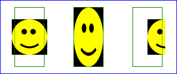
Example feImage illustrates how
images are placed relative to an object. From left to right:
- The default placement of an image. Note that the image is
centered in the filter region and
has the maximum size that will fit in the region consistent with
preserving the aspect ratio.
- The image stretched to fit the bounding box of an object.
- The image placed using user coordinates. Note that the image is
first centered in a box the size of the filter region and has the maximum
size that will fit in the box consistent with preserving the aspect
ratio. This box is then shifted by the given ‘
x’ and ‘y’ values relative to the viewport the
object is in.
<svg width="600" height="250" viewBox="0 0 600 250"
xmlns="http://www.w3.org/2000/svg"
xmlns:xlink="http://www.w3.org/1999/xlink">
<title>Example feImage - Examples of feImage use</title>
<desc>Three examples of using feImage, the first showing the
default rendering, the second showing the image fit
to a box and the third showing the image
shifted and clipped.</desc>
<defs>
<filter id="Default">
<feImage xlink:href="smiley.png" />
</filter>
<filter id="Fitted" primitiveUnits="objectBoundingBox">
<feImage xlink:href="smiley.png"
x="0" y="0" width="100%" height="100%"
preserveAspectRatio="none"/>
</filter>
<filter id="Shifted">
<feImage xlink:href="smiley.png"
x="500" y="5"/>
</filter>
</defs>
<rect fill="none" stroke="blue"
x="1" y="1" width="598" height="248"/>
<g>
<rect x="50" y="25" width="100" height="200" filter="url(#Default)"/>
<rect x="50" y="25" width="100" height="200" fill="none" stroke="green"/>
<rect x="250" y="25" width="100" height="200" filter="url(#Fitted)"/>
<rect x="250" y="25" width="100" height="200" fill="none" stroke="green"/>
<rect x="450" y="25" width="100" height="200" filter="url(#Shifted)"/>
<rect x="450" y="25" width="100" height="200" fill="none" stroke="green"/>
</g>
</svg>
Example feImage
|
View this
example as SVG (SVG-enabled browsers only)
24. Filter primitive ‘feMerge’
| Name:
| feMerge
|
| Categories:
| Filter primitive
element
|
| Content model:
| Any number of the following elements, in any order:
|
| Attributes:
|
- core
attributes — ‘id’, ‘xml:base’, ‘xml:lang’, ‘xml:space’
- presentation
attributes — ‘alignment-baseline’, ‘baseline-shift’, ‘clip’, ‘clip-path’, ‘clip-rule’, ‘color’, ‘color-interpolation’, ‘color-interpolation-filters’, ‘color-profile’, ‘color-rendering’, ‘cursor’, ‘direction’, ‘display’, ‘dominant-baseline’, ‘enable-background’, ‘fill’, ‘fill-opacity’, ‘fill-rule’, ‘filter’, ‘flood-color’, ‘flood-opacity’, ‘font’, ‘font-family’, ‘font-size’, ‘font-size-adjust’, ‘font-stretch’, ‘font-style’, ‘font-variant’, ‘font-weight’, ‘glyph-orientation-horizontal’, ‘glyph-orientation-vertical’, ‘image-rendering’, ‘kerning’, ‘letter-spacing’, ‘lighting-color’, ‘marker’, ‘marker-end’, ‘marker-mid’, ‘marker-start’, ‘mask’, ‘opacity’, ‘overflow’, ‘pointer-events’, ‘shape-rendering’, ‘stop-color’, ‘stop-opacity’, ‘stroke’, ‘stroke-dasharray’, ‘stroke-dashoffset’, ‘stroke-linecap’, ‘stroke-linejoin’, ‘stroke-miterlimit’, ‘stroke-opacity’, ‘stroke-width’, ‘text-anchor’, ‘text-decoration’, ‘text-rendering’, ‘unicode-bidi’, ‘visibility’, ‘word-spacing’, ‘writing-mode’
- filter primitive
attributes — ‘x’, ‘y’, ‘width’, ‘height’, ‘result’
- ‘class’
- ‘style’
|
| DOM Interfaces:
| SVGFEMergeElement
|
This filter primitive composites input image layers on top of each
other using the over operator with Input1
(corresponding to the first ‘feMergeNode’ child element) on the
bottom and the last specified input, InputN (corresponding to
the last ‘feMergeNode’ child element), on
top.
Many effects produce a number of intermediate layers in order to
create the final output image. This filter allows us to collapse those
into a single image. Although this could be done by using n-1
Composite-filters, it is more convenient to have this common operation
available in this form, and offers the implementation some additional
flexibility.
Each ‘feMerge’ element can have any number of
‘feMergeNode’ subelements, each of which
has an in
attribute.
| Name:
| feMergeNode
|
| Categories:
| None.
|
| Content model:
| Any number of the following elements, in any order:
|
| Attributes:
|
|
| DOM Interfaces:
| SVGFEMergeNodeElement
|
The canonical implementation of feMerge is to render the entire
effect into one RGBA layer, and then render the resulting layer on the
output device. In certain cases (in particular if the output device
itself is a continuous tone device), and since merging is associative,
it might be a sufficient approximation to evaluate the effect one
layer at a time and render each layer individually onto the output
device bottom to top.
If the topmost image input is SourceGraphic and this ‘feMerge’ is the last filter primitive in
the filter, the implementation is encouraged to render the layers up
to that point, and then render the SourceGraphic directly from its vector
description on top.
The example at the start of
this chapter makes use of the feMerge filter primitive to composite two
intermediate filter results together.
| Name:
| feMorphology
|
| Categories:
| Filter primitive
element
|
| Content model:
| Any number of the following elements, in any order:
|
| Attributes:
|
- core
attributes — ‘id’, ‘xml:base’, ‘xml:lang’, ‘xml:space’
- presentation
attributes — ‘alignment-baseline’, ‘baseline-shift’, ‘clip’, ‘clip-path’, ‘clip-rule’, ‘color’, ‘color-interpolation’, ‘color-interpolation-filters’, ‘color-profile’, ‘color-rendering’, ‘cursor’, ‘direction’, ‘display’, ‘dominant-baseline’, ‘enable-background’, ‘fill’, ‘fill-opacity’, ‘fill-rule’, ‘filter’, ‘flood-color’, ‘flood-opacity’, ‘font’, ‘font-family’, ‘font-size’, ‘font-size-adjust’, ‘font-stretch’, ‘font-style’, ‘font-variant’, ‘font-weight’, ‘glyph-orientation-horizontal’, ‘glyph-orientation-vertical’, ‘image-rendering’, ‘kerning’, ‘letter-spacing’, ‘lighting-color’, ‘marker’, ‘marker-end’, ‘marker-mid’, ‘marker-start’, ‘mask’, ‘opacity’, ‘overflow’, ‘pointer-events’, ‘shape-rendering’, ‘stop-color’, ‘stop-opacity’, ‘stroke’, ‘stroke-dasharray’, ‘stroke-dashoffset’, ‘stroke-linecap’, ‘stroke-linejoin’, ‘stroke-miterlimit’, ‘stroke-opacity’, ‘stroke-width’, ‘text-anchor’, ‘text-decoration’, ‘text-rendering’, ‘unicode-bidi’, ‘visibility’, ‘word-spacing’, ‘writing-mode’
- filter primitive
attributes — ‘x’, ‘y’, ‘width’, ‘height’, ‘result’
- ‘class’
- ‘style’
- ‘in’
- ‘operator’
- ‘radius’
|
| DOM Interfaces:
| SVGFEMorphologyElement
|
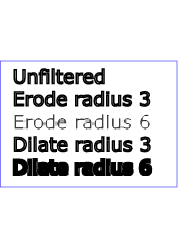
This filter primitive performs "fattening" or "thinning" of
artwork. It is particularly useful for fattening or thinning an alpha
channel.
The dilation (or erosion) kernel is a rectangle with a width of
2*x-radius and a height of 2*y-radius. In dilation,
the output pixel is the individual component-wise maximum of the
corresponding R,G,B,A values in the input image's kernel rectangle. In
erosion, the output pixel is the individual component-wise minimum of
the corresponding R,G,B,A values in the input image's kernel
rectangle.
Frequently this operation will take place on alpha-only images,
such as that produced by the built-in input, SourceAlpha. In
that case, the implementation might want to optimize the single
channel case.
If the input has infinite extent and is constant (e.g FillPaint where the
fill is a solid color), this operation has no effect. If the input has
infinite extent and the filter result is the input to an ‘feTile’, the filter is evaluated with
periodic boundary conditions.
By default, the subregion interacts as input and output
clipping and this sentence would be irrelevant. However, this changes
if the WG decides to allow a choice between input and output clipping.
What about other inputs with infinite extends? What is
the ‘periodic boundary condition’?
Because ‘feMorphology’ operates on premultipied
color values, it will always result in color values less than or equal
to the alpha channel.
Attribute definitions:
- operator
= "erode | dilate"
- A keyword indicating whether to erode (i.e., thin) or dilate
(fatten) the source graphic. The lacuna value for ‘
operator’ is erode.
Animatable: yes.
- radius =
"<number-optional-number>"
- The radius (or radii) for the operation. If two <number>
s are provided, the first number represents a x-radius and the
second value represents a y-radius. If one number is provided, then
that value is used for both X and Y. The values are in the
coordinate system established by attribute ‘
primitiveUnits’ on the ‘filter’ element.
A negative or zero value disables the effect of the given filter
primitive (i.e., the result is a transparent black image).
If the attribute is not specified, then the effect is as if a value
of 0 were specified.
Animatable: yes.
<?xml version="1.0"?>
<!DOCTYPE svg PUBLIC "-//W3C//DTD SVG 1.1//EN"
"http://www.w3.org/Graphics/SVG/1.1/DTD/svg11.dtd">
<svg width="5cm" height="7cm" viewBox="0 0 700 500"
xmlns="http://www.w3.org/2000/svg" version="1.1">
<title>Example feMorphology - Examples of erode and dilate</title>
<desc>Five text strings drawn as outlines.
The first is unfiltered. The second and third use 'erode'.
The fourth and fifth use 'dilate'.</desc>
<defs>
<filter id="Erode3">
<feMorphology operator="erode" in="SourceGraphic" radius="3" />
</filter>
<filter id="Erode6">
<feMorphology operator="erode" in="SourceGraphic" radius="6" />
</filter>
<filter id="Dilate3">
<feMorphology operator="dilate" in="SourceGraphic" radius="3" />
</filter>
<filter id="Dilate6">
<feMorphology operator="dilate" in="SourceGraphic" radius="6" />
</filter>
</defs>
<rect fill="none" stroke="blue" stroke-width="2"
x="1" y="1" width="698" height="498"/>
<g enable-background="new" >
<g font-family="Verdana" font-size="75"
fill="none" stroke="black" stroke-width="6" >
<text x="50" y="90">Unfiltered</text>
<text x="50" y="180" filter="url(#Erode3)" >Erode radius 3</text>
<text x="50" y="270" filter="url(#Erode6)" >Erode radius 6</text>
<text x="50" y="360" filter="url(#Dilate3)" >Dilate radius 3</text>
<text x="50" y="450" filter="url(#Dilate6)" >Dilate radius 6</text>
</g>
</g>
</svg>
Example
|
View this
example as SVG (SVG-enabled browsers only)
26. Filter primitive ‘feOffset’
| Name:
| feOffset
|
| Categories:
| Filter primitive
element
|
| Content model:
| Any number of the following elements, in any order:
|
| Attributes:
|
- core
attributes — ‘id’, ‘xml:base’, ‘xml:lang’, ‘xml:space’
- presentation
attributes — ‘alignment-baseline’, ‘baseline-shift’, ‘clip’, ‘clip-path’, ‘clip-rule’, ‘color’, ‘color-interpolation’, ‘color-interpolation-filters’, ‘color-profile’, ‘color-rendering’, ‘cursor’, ‘direction’, ‘display’, ‘dominant-baseline’, ‘enable-background’, ‘fill’, ‘fill-opacity’, ‘fill-rule’, ‘filter’, ‘flood-color’, ‘flood-opacity’, ‘font’, ‘font-family’, ‘font-size’, ‘font-size-adjust’, ‘font-stretch’, ‘font-style’, ‘font-variant’, ‘font-weight’, ‘glyph-orientation-horizontal’, ‘glyph-orientation-vertical’, ‘image-rendering’, ‘kerning’, ‘letter-spacing’, ‘lighting-color’, ‘marker’, ‘marker-end’, ‘marker-mid’, ‘marker-start’, ‘mask’, ‘opacity’, ‘overflow’, ‘pointer-events’, ‘shape-rendering’, ‘stop-color’, ‘stop-opacity’, ‘stroke’, ‘stroke-dasharray’, ‘stroke-dashoffset’, ‘stroke-linecap’, ‘stroke-linejoin’, ‘stroke-miterlimit’, ‘stroke-opacity’, ‘stroke-width’, ‘text-anchor’, ‘text-decoration’, ‘text-rendering’, ‘unicode-bidi’, ‘visibility’, ‘word-spacing’, ‘writing-mode’
- filter primitive
attributes — ‘x’, ‘y’, ‘width’, ‘height’, ‘result’
- ‘class’
- ‘style’
- ‘in’
- ‘dx’
- ‘dy’
|
| DOM Interfaces:
| SVGFEOffsetElement
|
This filter primitive offsets the input image relative to its
current position in the image space by the specified vector.
This is important for effects like drop shadows.
When applying this filter, the destination location may be offset
by a fraction of a pixel in device space. In this case a high quality viewer
should make use of appropriate interpolation techniques, for example
bilinear or bicubic. This is especially recommended for dynamic
viewers where this interpolation provides visually smoother movement
of images. For static viewers this is less of a concern. Close
attention should be made to the ‘image-rendering’ property setting to
determine the authors intent.
Attribute definitions:
- dx = "<number>"
- The amount to offset the input graphic along the x-axis. The
offset amount is expressed in the coordinate system established by
attribute ‘
primitiveUnits’ on the ‘filter’ element.
If the attribute is not specified, then the effect is as if a value
of 0 were specified.
Animatable: yes.
- dy = "<number>"
- The amount to offset the input graphic along the y-axis. The
offset amount is expressed in the coordinate system established by
attribute ‘
primitiveUnits’ on the ‘filter’ element.
If the attribute is not specified, then the effect is as if a value
of 0 were specified.
Animatable: yes.
The example at the start of this chapter
makes use of the feOffset
filter primitive to offset the drop shadow from the original source
graphic.
| Name:
| feSpecularLighting
|
| Categories:
| Filter primitive
element
|
| Content model:
| Any number of descriptive
elements and exactly one light source element, in any
order.
|
| Attributes:
|
- core
attributes — ‘id’, ‘xml:base’, ‘xml:lang’, ‘xml:space’
- presentation
attributes — ‘alignment-baseline’, ‘baseline-shift’, ‘clip’, ‘clip-path’, ‘clip-rule’, ‘color’, ‘color-interpolation’, ‘color-interpolation-filters’, ‘color-profile’, ‘color-rendering’, ‘cursor’, ‘direction’, ‘display’, ‘dominant-baseline’, ‘enable-background’, ‘fill’, ‘fill-opacity’, ‘fill-rule’, ‘filter’, ‘flood-color’, ‘flood-opacity’, ‘font’, ‘font-family’, ‘font-size’, ‘font-size-adjust’, ‘font-stretch’, ‘font-style’, ‘font-variant’, ‘font-weight’, ‘glyph-orientation-horizontal’, ‘glyph-orientation-vertical’, ‘image-rendering’, ‘kerning’, ‘letter-spacing’, ‘lighting-color’, ‘marker’, ‘marker-end’, ‘marker-mid’, ‘marker-start’, ‘mask’, ‘opacity’, ‘overflow’, ‘pointer-events’, ‘shape-rendering’, ‘stop-color’, ‘stop-opacity’, ‘stroke’, ‘stroke-dasharray’, ‘stroke-dashoffset’, ‘stroke-linecap’, ‘stroke-linejoin’, ‘stroke-miterlimit’, ‘stroke-opacity’, ‘stroke-width’, ‘text-anchor’, ‘text-decoration’, ‘text-rendering’, ‘unicode-bidi’, ‘visibility’, ‘word-spacing’, ‘writing-mode’
- filter primitive
attributes — ‘x’, ‘y’, ‘width’, ‘height’, ‘result’
- ‘class’
- ‘style’
- ‘in’
- ‘surfaceScale’
- ‘specularConstant’
- ‘specularExponent’
- ‘kernelUnitLength’
|
| DOM Interfaces:
| SVGFESpecularLightingElement
|
This filter primitive lights a source graphic using the alpha
channel as a bump map. The resulting image is an RGBA image based on
the light color. The lighting calculation follows the standard
specular component of the Phong lighting model. The resulting image
depends on the light color, light position and surface geometry of the
input bump map. The result of the lighting calculation is added. The
filter primitive assumes that the viewer is at infinity in the z
direction (i.e., the unit vector in the eye direction is (0,0,1)
everywhere).
This filter primitive produces an image which contains the specular
reflection part of the lighting calculation. Such a map is intended to
be combined with a texture using the add term of the
arithmetic ‘feComposite’ method. Multiple light
sources can be simulated by adding several of these light maps before
applying it to the texture image.
The resulting RGBA image is computed as follows:
Sr = ks * pow(N.H,
specularExponent) * Lr
Sg = ks * pow(N.H, specularExponent) *
Lg
Sb = ks * pow(N.H, specularExponent) *
Lb
Sa = max(Sr, Sg,
Sb)
where
- ks = specular lighting constant
N = surface normal unit vector, a function of x and y
H = "halfway" unit vector between eye unit vector and light unit
vector
Lr,Lg,Lb = RGB components of light
See ‘feDiffuseLighting’ for definition
of N and (Lr, Lg, Lb).
The definition of H reflects our assumption of the constant eye
vector E = (0,0,1):
H = (L + E) / Norm(L+E)
where L is the light unit vector.
Unlike the ‘feDiffuseLighting’, the ‘feSpecularLighting’ filter produces a
non-opaque image. This is due to the fact that the specular result
(Sr,Sg,Sb,Sa) is meant to
be added to the textured image. The alpha channel of the result is the
max of the color components, so that where the specular light is zero,
no additional coverage is added to the image and a fully white
highlight will add opacity.
The ‘feDiffuseLighting’ and ‘feSpecularLighting’ filters will often be
applied together. An implementation may detect this and calculate both
maps in one pass, instead of two.
Attribute definitions:
- surfaceScale = "<number>"
- height of surface when Ain = 1.
If the attribute is not specified, then the effect is as if a value
of 1 were specified.
Animatable: yes.
- specularConstant = "<number>"
- ks in Phong lighting model. In SVG, this can be any non-negative
number.
If the attribute is not specified, then the effect is as if a value
of 1 were specified.
Animatable: yes.
- specularExponent = "<number>"
- Exponent for specular term, larger is more "shiny". Range 1.0 to
128.0.
If the attribute is not specified, then the effect is as if a value
of 1 were specified.
Animatable: yes.
- kernelUnitLength = "<number-optional-number>"
- The first number is the <dx> value. The second number is
the <dy> value. If the <dy> value is not specified, it
defaults to the same value as <dx>. Indicates the intended
distance in current filter units (i.e., units as determined by the
value of attribute ‘
primitiveUnits’) for dx and
dy, respectively, in the surface normal calculation
formulas. By specifying value(s) for kernelUnitLength, the kernel becomes defined
in a scalable, abstract coordinate system. If kernelUnitLength is not specified, the
dx and dy values should represent very
small deltas relative to a given (x,y) position, which
might be implemented in some cases as one pixel in the intermediate
image offscreen bitmap, which is a pixel-based coordinate system,
and thus potentially not scalable. For some level of consistency
across display media and user agents, it is necessary that a value
be provided for at least one of filterRes and kernelUnitLength. Discussion of intermediate
images are in the Introduction and in
the description of attribute ‘filterRes’.
If a negative or zero value is specified the default value will be
used instead.
Animatable: yes.
The light source is defined by one of the child elements ‘feDistantLight’, ‘fePointLight’ or ‘feDistantLight’. The light color is
specified by property ‘lighting-color’.
The example at the start of this chapter
makes use of the feSpecularLighting filter primitive to
achieve a highly reflective, 3D glowing effect.
28. Filter primitive ‘feTile’
| Name:
| feTile
|
| Categories:
| Filter primitive
element
|
| Content model:
| Any number of the following elements, in any order:
|
| Attributes:
|
- core
attributes — ‘id’, ‘xml:base’, ‘xml:lang’, ‘xml:space’
- presentation
attributes — ‘alignment-baseline’, ‘baseline-shift’, ‘clip’, ‘clip-path’, ‘clip-rule’, ‘color’, ‘color-interpolation’, ‘color-interpolation-filters’, ‘color-profile’, ‘color-rendering’, ‘cursor’, ‘direction’, ‘display’, ‘dominant-baseline’, ‘enable-background’, ‘fill’, ‘fill-opacity’, ‘fill-rule’, ‘filter’, ‘flood-color’, ‘flood-opacity’, ‘font’, ‘font-family’, ‘font-size’, ‘font-size-adjust’, ‘font-stretch’, ‘font-style’, ‘font-variant’, ‘font-weight’, ‘glyph-orientation-horizontal’, ‘glyph-orientation-vertical’, ‘image-rendering’, ‘kerning’, ‘letter-spacing’, ‘lighting-color’, ‘marker’, ‘marker-end’, ‘marker-mid’, ‘marker-start’, ‘mask’, ‘opacity’, ‘overflow’, ‘pointer-events’, ‘shape-rendering’, ‘stop-color’, ‘stop-opacity’, ‘stroke’, ‘stroke-dasharray’, ‘stroke-dashoffset’, ‘stroke-linecap’, ‘stroke-linejoin’, ‘stroke-miterlimit’, ‘stroke-opacity’, ‘stroke-width’, ‘text-anchor’, ‘text-decoration’, ‘text-rendering’, ‘unicode-bidi’, ‘visibility’, ‘word-spacing’, ‘writing-mode’
- filter primitive
attributes — ‘x’, ‘y’, ‘width’, ‘height’, ‘result’
- ‘class’
- ‘style’
- ‘in’
|
| DOM Interfaces:
| SVGFETileElement
|
This filter primitive fills a target rectangle with a repeated,
tiled pattern of an input image. The target rectangle is as large as
the filter primitive subregion
established by the ‘feTile’ element.
Typically, the input image has been defined with its own filter primitive subregion in
order to define a reference tile. ‘feTile’ replicates
the reference tile in both X and Y to completely fill the target
rectangle. The top/left corner of each given tile is at location
(x+i*width,y+j*height), where (x,y)
represents the top/left of the input image's filter primitive subregion,
width and height represent the width and
height of the input image's filter
primitive subregion, and i and j can be
any integer value. In most cases, the input image will have a smaller
filter primitive subregion
than the ‘feTile’ in order to achieve a repeated
pattern effect.
Implementers must take
appropriate measures in constructing the tiled image to avoid
artifacts between tiles, particularly in situations where the user to
device transform includes shear and/or rotation. Unless care is taken,
interpolation can lead to edge pixels in the tile having opacity
values lower or higher than expected due to the interaction of
painting adjacent tiles which each have partial overlap with
particular pixels.
| Name:
| feTurbulence
|
| Categories:
| Filter primitive
element
|
| Content model:
| Any number of the following elements, in any order:
|
| Attributes:
|
- core
attributes — ‘id’, ‘xml:base’, ‘xml:lang’, ‘xml:space’
- presentation
attributes — ‘alignment-baseline’, ‘baseline-shift’, ‘clip’, ‘clip-path’, ‘clip-rule’, ‘color’, ‘color-interpolation’, ‘color-interpolation-filters’, ‘color-profile’, ‘color-rendering’, ‘cursor’, ‘direction’, ‘display’, ‘dominant-baseline’, ‘enable-background’, ‘fill’, ‘fill-opacity’, ‘fill-rule’, ‘filter’, ‘flood-color’, ‘flood-opacity’, ‘font’, ‘font-family’, ‘font-size’, ‘font-size-adjust’, ‘font-stretch’, ‘font-style’, ‘font-variant’, ‘font-weight’, ‘glyph-orientation-horizontal’, ‘glyph-orientation-vertical’, ‘image-rendering’, ‘kerning’, ‘letter-spacing’, ‘lighting-color’, ‘marker’, ‘marker-end’, ‘marker-mid’, ‘marker-start’, ‘mask’, ‘opacity’, ‘overflow’, ‘pointer-events’, ‘shape-rendering’, ‘stop-color’, ‘stop-opacity’, ‘stroke’, ‘stroke-dasharray’, ‘stroke-dashoffset’, ‘stroke-linecap’, ‘stroke-linejoin’, ‘stroke-miterlimit’, ‘stroke-opacity’, ‘stroke-width’, ‘text-anchor’, ‘text-decoration’, ‘text-rendering’, ‘unicode-bidi’, ‘visibility’, ‘word-spacing’, ‘writing-mode’
- filter primitive
attributes — ‘x’, ‘y’, ‘width’, ‘height’, ‘result’
- ‘class’
- ‘style’
- ‘baseFrequency’
- ‘numOctaves’
- ‘seed’
- ‘stitchTiles’
- ‘type’
|
| DOM Interfaces:
| SVGFETurbulenceElement
|
Consider phasing out this C algorithm in favor of
Simplex noise, which is more HW friendly.
This filter primitive creates an image using the Perlin turbulence
function. It allows the synthesis of artificial textures like clouds
or marble. For a detailed description the of the Perlin turbulence
function, see "Texturing and Modeling", Ebert et al, AP Professional,
1994. The resulting image will fill the entire filter primitive subregion for
this filter primitive.
It is possible to create bandwidth-limited noise by synthesizing
only one octave.
The C code below shows the exact algorithm used for this filter
effect. The filter primitive
subregion is to be passed as the arguments fTileX, fTileY,
fTileWidth and fTileHeight.
For fractalSum, you get a turbFunctionResult that is aimed at a
range of -1 to 1 (the actual result might exceed this range in some
cases). To convert to a color value, use the formula colorValue
= ((turbFunctionResult * 255) + 255) / 2, then clamp to the
range 0 to 255.
For turbulence, you get a turbFunctionResult that is aimed at a
range of 0 to 1 (the actual result might exceed this range in some
cases). To convert to a color value, use the formula colorValue
= (turbFunctionResult * 255), then clamp to the range 0 to 255.
The following order is used for applying the pseudo random numbers.
An initial seed value is computed based on the ‘seed’ attribute. Then the implementation
computes the lattice points for R, then continues getting additional
pseudo random numbers relative to the last generated pseudo random
number and computes the lattice points for G, and so on for B and A.
The generated color and alpha values are in the color space
determined by the ‘color-interpolation-filters’ property:
/* Produces results in the range [1, 2**31 - 2].
Algorithm is: r = (a * r) mod m
where a = 16807 and m = 2**31 - 1 = 2147483647
See [Park & Miller], CACM vol. 31 no. 10 p. 1195, Oct. 1988
To test: the algorithm should produce the result 1043618065
as the 10,000th generated number if the original seed is 1.
*/
#define RAND_m 2147483647 /* 2**31 - 1 */
#define RAND_a 16807 /* 7**5; primitive root of m */
#define RAND_q 127773 /* m / a */
#define RAND_r 2836 /* m % a */
long setup_seed(long lSeed)
{
if (lSeed <= 0) lSeed = -(lSeed % (RAND_m - 1)) + 1;
if (lSeed > RAND_m - 1) lSeed = RAND_m - 1;
return lSeed;
}
long random(long lSeed)
{
long result;
result = RAND_a * (lSeed % RAND_q) - RAND_r * (lSeed / RAND_q);
if (result <= 0) result += RAND_m;
return result;
}
#define BSize 0x100
#define BM 0xff
#define PerlinN 0x1000
#define NP 12 /* 2^PerlinN */
#define NM 0xfff
static uLatticeSelector[BSize + BSize + 2];
static double fGradient[4][BSize + BSize + 2][2];
struct StitchInfo
{
int nWidth; // How much to subtract to wrap for stitching.
int nHeight;
int nWrapX; // Minimum value to wrap.
int nWrapY;
};
static void init(long lSeed)
{
double s;
int i, j, k;
lSeed = setup_seed(lSeed);
for(k = 0; k < 4; k++)
{
for(i = 0; i < BSize; i++)
{
uLatticeSelector[i] = i;
for (j = 0; j < 2; j++)
fGradient[k][i][j] = (double)(((lSeed = random(lSeed)) % (BSize + BSize)) - BSize) / BSize;
s = double(sqrt(fGradient[k][i][0] * fGradient[k][i][0] + fGradient[k][i][1] * fGradient[k][i][1]));
fGradient[k][i][0] /= s;
fGradient[k][i][1] /= s;
}
}
while(--i)
{
k = uLatticeSelector[i];
uLatticeSelector[i] = uLatticeSelector[j = (lSeed = random(lSeed)) % BSize];
uLatticeSelector[j] = k;
}
for(i = 0; i < BSize + 2; i++)
{
uLatticeSelector[BSize + i] = uLatticeSelector[i];
for(k = 0; k < 4; k++)
for(j = 0; j < 2; j++)
fGradient[k][BSize + i][j] = fGradient[k][i][j];
}
}
#define s_curve(t) ( t * t * (3. - 2. * t) )
#define lerp(t, a, b) ( a + t * (b - a) )
double noise2(int nColorChannel, double vec[2], StitchInfo *pStitchInfo)
{
int bx0, bx1, by0, by1, b00, b10, b01, b11;
double rx0, rx1, ry0, ry1, *q, sx, sy, a, b, t, u, v;
register i, j;
t = vec[0] + PerlinN;
bx0 = (int)t;
bx1 = bx0+1;
rx0 = t - (int)t;
rx1 = rx0 - 1.0f;
t = vec[1] + PerlinN;
by0 = (int)t;
by1 = by0+1;
ry0 = t - (int)t;
ry1 = ry0 - 1.0f;
// If stitching, adjust lattice points accordingly.
if(pStitchInfo != NULL)
{
if(bx0 >= pStitchInfo->nWrapX)
bx0 -= pStitchInfo->nWidth;
if(bx1 >= pStitchInfo->nWrapX)
bx1 -= pStitchInfo->nWidth;
if(by0 >= pStitchInfo->nWrapY)
by0 -= pStitchInfo->nHeight;
if(by1 >= pStitchInfo->nWrapY)
by1 -= pStitchInfo->nHeight;
}
bx0 &= BM;
bx1 &= BM;
by0 &= BM;
by1 &= BM;
i = uLatticeSelector[bx0];
j = uLatticeSelector[bx1];
b00 = uLatticeSelector[i + by0];
b10 = uLatticeSelector[j + by0];
b01 = uLatticeSelector[i + by1];
b11 = uLatticeSelector[j + by1];
sx = double(s_curve(rx0));
sy = double(s_curve(ry0));
q = fGradient[nColorChannel][b00]; u = rx0 * q[0] + ry0 * q[1];
q = fGradient[nColorChannel][b10]; v = rx1 * q[0] + ry0 * q[1];
a = lerp(sx, u, v);
q = fGradient[nColorChannel][b01]; u = rx0 * q[0] + ry1 * q[1];
q = fGradient[nColorChannel][b11]; v = rx1 * q[0] + ry1 * q[1];
b = lerp(sx, u, v);
return lerp(sy, a, b);
}
double turbulence(int nColorChannel, double *point, double fBaseFreqX, double fBaseFreqY,
int nNumOctaves, bool bFractalSum, bool bDoStitching,
double fTileX, double fTileY, double fTileWidth, double fTileHeight)
{
StitchInfo stitch;
StitchInfo *pStitchInfo = NULL; // Not stitching when NULL.
// Adjust the base frequencies if necessary for stitching.
if(bDoStitching)
{
// When stitching tiled turbulence, the frequencies must be adjusted
// so that the tile borders will be continuous.
if(fBaseFreqX != 0.0)
{
double fLoFreq = double(floor(fTileWidth * fBaseFreqX)) / fTileWidth;
double fHiFreq = double(ceil(fTileWidth * fBaseFreqX)) / fTileWidth;
if(fBaseFreqX / fLoFreq < fHiFreq / fBaseFreqX)
fBaseFreqX = fLoFreq;
else
fBaseFreqX = fHiFreq;
}
if(fBaseFreqY != 0.0)
{
double fLoFreq = double(floor(fTileHeight * fBaseFreqY)) / fTileHeight;
double fHiFreq = double(ceil(fTileHeight * fBaseFreqY)) / fTileHeight;
if(fBaseFreqY / fLoFreq < fHiFreq / fBaseFreqY)
fBaseFreqY = fLoFreq;
else
fBaseFreqY = fHiFreq;
}
// Set up initial stitch values.
pStitchInfo = &stitch;
stitch.nWidth = int(fTileWidth * fBaseFreqX + 0.5f);
stitch.nWrapX = fTileX * fBaseFreqX + PerlinN + stitch.nWidth;
stitch.nHeight = int(fTileHeight * fBaseFreqY + 0.5f);
stitch.nWrapY = fTileY * fBaseFreqY + PerlinN + stitch.nHeight;
}
double fSum = 0.0f;
double vec[2];
vec[0] = point[0] * fBaseFreqX;
vec[1] = point[1] * fBaseFreqY;
double ratio = 1;
for(int nOctave = 0; nOctave < nNumOctaves; nOctave++)
{
if(bFractalSum)
fSum += double(noise2(nColorChannel, vec, pStitchInfo) / ratio);
else
fSum += double(fabs(noise2(nColorChannel, vec, pStitchInfo)) / ratio);
vec[0] *= 2;
vec[1] *= 2;
ratio *= 2;
if(pStitchInfo != NULL)
{
// Update stitch values. Subtracting PerlinN before the multiplication and
// adding it afterward simplifies to subtracting it once.
stitch.nWidth *= 2;
stitch.nWrapX = 2 * stitch.nWrapX - PerlinN;
stitch.nHeight *= 2;
stitch.nWrapY = 2 * stitch.nWrapY - PerlinN;
}
}
return fSum;
}
Attribute definitions:
- baseFrequency = "<number-optional-number>"
-
The base frequency (frequencies) parameter(s) for the noise
function. If two <number>s
are provided, the first number represents a base frequency in the X
direction and the second value represents a base frequency in the Y
direction. If one number is provided, then that value is used for
both X and Y.
The lacuna
value for ‘baseFrequency’ is 0.
Negative values are unsupported.
Animatable: yes.
- numOctaves = "<integer>"
-
The numOctaves parameter for the noise function.
The lacuna
value for ‘numOctaves’ is 1.
Negative values
are unsupported.
Animatable: yes.
- seed =
"<number>"
-
The starting number for the pseudo random number generator.
The
lacuna
value for ‘seed’ is 0.
When
the seed number is handed over to the algorithm above it must first
be truncated, i.e. rounded to the closest integer value towards
zero.
Animatable: yes.
- stitchTiles = "stitch | noStitch"
-
If stitchTiles="noStitch", no
attempt it made to achieve smooth transitions at the border of
tiles which contain a turbulence function. Sometimes the result
will show clear discontinuities at the tile borders.
If stitchTiles="stitch", then the
user agent will automatically adjust baseFrequency-x and
baseFrequency-y values such that the ‘feTurbulence’ node's width and height
(i.e., the width and height of the current subregion) contains an
integral number of the Perlin tile width and height for the first
octave. The baseFrequency will be adjusted up or down depending on
which way has the smallest relative (not absolute) change as
follows: Given the frequency, calculate
lowFreq=floor(width*frequency)/width and
hiFreq=ceil(width*frequency)/width. If
frequency/lowFreq < hiFreq/frequency then use lowFreq, else use
hiFreq. While generating turbulence values, generate lattice
vectors as normal for Perlin Noise, except for those lattice points
that lie on the right or bottom edges of the active area (the size
of the resulting tile). In those cases, copy the lattice vector
from the opposite edge of the active area.
The lacuna
value for ‘stitchTiles’ is noStitch.
Animatable: yes.
- type =
"fractalNoise | turbulence"
-
Indicates whether the filter primitive should perform a noise or
turbulence function.
The
lacuna
value for ‘type’ is turbulence.
Animatable: yes.
<?xml version="1.0"?>
<!DOCTYPE svg PUBLIC "-//W3C//DTD SVG 1.1//EN"
"http://www.w3.org/Graphics/SVG/1.1/DTD/svg11.dtd">
<svg width="450px" height="325px" viewBox="0 0 450 325"
xmlns="http://www.w3.org/2000/svg" version="1.1">
<title>Example feTurbulence - Examples of feTurbulence operations</title>
<desc>Six rectangular areas showing the effects of
various parameter settings for feTurbulence.</desc>
<g font-family="Verdana" text-anchor="middle" font-size="10" >
<defs>
<filter id="Turb1" filterUnits="objectBoundingBox"
x="0%" y="0%" width="100%" height="100%">
<feTurbulence type="turbulence" baseFrequency="0.05" numOctaves="2"/>
</filter>
<filter id="Turb2" filterUnits="objectBoundingBox"
x="0%" y="0%" width="100%" height="100%">
<feTurbulence type="turbulence" baseFrequency="0.1" numOctaves="2"/>
</filter>
<filter id="Turb3" filterUnits="objectBoundingBox"
x="0%" y="0%" width="100%" height="100%">
<feTurbulence type="turbulence" baseFrequency="0.05" numOctaves="8"/>
</filter>
<filter id="Turb4" filterUnits="objectBoundingBox"
x="0%" y="0%" width="100%" height="100%">
<feTurbulence type="fractalNoise" baseFrequency="0.1" numOctaves="4"/>
</filter>
<filter id="Turb5" filterUnits="objectBoundingBox"
x="0%" y="0%" width="100%" height="100%">
<feTurbulence type="fractalNoise" baseFrequency="0.4" numOctaves="4"/>
</filter>
<filter id="Turb6" filterUnits="objectBoundingBox"
x="0%" y="0%" width="100%" height="100%">
<feTurbulence type="fractalNoise" baseFrequency="0.1" numOctaves="1"/>
</filter>
</defs>
<rect x="1" y="1" width="448" height="323"
fill="none" stroke="blue" stroke-width="1" />
<rect x="25" y="25" width="100" height="75" filter="url(#Turb1)" />
<text x="75" y="117">type=turbulence</text>
<text x="75" y="129">baseFrequency=0.05</text>
<text x="75" y="141">numOctaves=2</text>
<rect x="175" y="25" width="100" height="75" filter="url(#Turb2)" />
<text x="225" y="117">type=turbulence</text>
<text x="225" y="129">baseFrequency=0.1</text>
<text x="225" y="141">numOctaves=2</text>
<rect x="325" y="25" width="100" height="75" filter="url(#Turb3)" />
<text x="375" y="117">type=turbulence</text>
<text x="375" y="129">baseFrequency=0.05</text>
<text x="375" y="141">numOctaves=8</text>
<rect x="25" y="180" width="100" height="75" filter="url(#Turb4)" />
<text x="75" y="272">type=fractalNoise</text>
<text x="75" y="284">baseFrequency=0.1</text>
<text x="75" y="296">numOctaves=4</text>
<rect x="175" y="180" width="100" height="75" filter="url(#Turb5)" />
<text x="225" y="272">type=fractalNoise</text>
<text x="225" y="284">baseFrequency=0.4</text>
<text x="225" y="296">numOctaves=4</text>
<rect x="325" y="180" width="100" height="75" filter="url(#Turb6)" />
<text x="375" y="272">type=fractalNoise</text>
<text x="375" y="284">baseFrequency=0.1</text>
<text x="375" y="296">numOctaves=1</text>
</g>
</svg>
Example
|
View this
example as SVG (SVG-enabled browsers only)
| Name:
| feDropShadow
|
| Categories:
| Filter primitive
element
|
| Content model:
| Any number of the following elements, in any order:
|
| Attributes:
|
- core
attributes — ‘id’, ‘xml:base’, ‘xml:lang’, ‘xml:space’
- presentation
attributes — ‘alignment-baseline’, ‘baseline-shift’, ‘clip’, ‘clip-path’, ‘clip-rule’, ‘color’, ‘color-interpolation’, ‘color-interpolation-filters’, ‘color-profile’, ‘color-rendering’, ‘cursor’, ‘direction’, ‘display’, ‘dominant-baseline’, ‘enable-background’, ‘fill’, ‘fill-opacity’, ‘fill-rule’, ‘filter’, ‘flood-color’, ‘flood-opacity’, ‘font’, ‘font-family’, ‘font-size’, ‘font-size-adjust’, ‘font-stretch’, ‘font-style’, ‘font-variant’, ‘font-weight’, ‘glyph-orientation-horizontal’, ‘glyph-orientation-vertical’, ‘image-rendering’, ‘kerning’, ‘letter-spacing’, ‘lighting-color’, ‘marker’, ‘marker-end’, ‘marker-mid’, ‘marker-start’, ‘mask’, ‘opacity’, ‘overflow’, ‘pointer-events’, ‘shape-rendering’, ‘stop-color’, ‘stop-opacity’, ‘stroke’, ‘stroke-dasharray’, ‘stroke-dashoffset’, ‘stroke-linecap’, ‘stroke-linejoin’, ‘stroke-miterlimit’, ‘stroke-opacity’, ‘stroke-width’, ‘text-anchor’, ‘text-decoration’, ‘text-rendering’, ‘unicode-bidi’, ‘visibility’, ‘word-spacing’, ‘writing-mode’
- filter primitive
attributes — ‘x’, ‘y’, ‘width’, ‘height’, ‘result’
- ‘class’
- ‘style’
- ‘in’
- ‘stdDeviation’
- ‘dx’
- ‘dy’
|
| DOM Interfaces:
| SVGFEDropShadowElement
|
This filter creates a drop shadow of the input image. It is a
shorthand filter, and is defined in terms of combinations of other filter primitives. The
expectation is that it can be optimized more easily by
implementations.
The result of a ‘feDropShadow’ filter primitive is
equivalent to the following:
<feGaussianBlur in="alpha-channel-of-feDropShadow-in" stdDeviation="stdDeviation-of-feDropShadow"/>
<feOffset dx="dx-of-feDropShadow" dy="dy-of-feDropShadow" result="offsetblur"/>
<feFlood flood-color="flood-color-of-feDropShadow" flood-opacity="flood-opacity-of-feDropShadow"/>
<feComposite in2="offsetblur" operator="in"/>
<feMerge>
<feMergeNode/>
<feMergeNode in="in-of-feDropShadow"/>
</feMerge>
The above divided into steps:
- Take the alpha channel of the input to the ‘
feDropShadow’ filter primitive and the ‘stdDeviation’ on the ‘feDropShadow’ and do processing as if the
following ‘feGaussianBlur’ was applied:
<feGaussianBlur in="alpha-channel-of-feDropShadow-in" stdDeviation="stdDeviation-of-feDropShadow"/>
- Offset the result of step 1 by ‘
dx’ and ‘dy’ as specified on the ‘feDropShadow’ element, equivalent to
applying an ‘feOffset’ with these parameters:
<feOffset dx="dx-of-feDropShadow" dy="dy-of-feDropShadow" result="offsetblur"/>
- Do processing as if an ‘
feFlood’
element with ‘flood-color’ and ‘flood-opacity’ as specified on the ‘feDropShadow’ was applied:
<feFlood flood-color="flood-color-of-feDropShadow" flood-opacity="flood-opacity-of-feDropShadow"/>
- Composite the result of the ‘
feFlood’ in step 3 with the result
of the ‘feOffset’ in step 2 as if an ‘feComposite’ filter primitive with operator=‘in’ was applied:
<feComposite in2="offsetblur" operator="in"/>
- Finally merge the result of the previous step, doing processing as
if the following ‘
feMerge’
was performed:
<feMerge>
<feMergeNode/>
<feMergeNode in="in-of-feDropShadow"/>
</feMerge>
Note that while the definition of the ‘feDropShadow’ filter primitive says that
it can be expanded into an equivalent tree it is not required that it
is implemented like that. The expectation is that user agents can
optimize the handling by not having to do all the steps separately.
Beyond the DOM interface SVGFEDropShadowElement
there is no way of accessing the internals of the ‘feDropShadow’ filter primitive, meaning
if the
filter primitive is implemented as an equivalent tree then that tree
must not be exposed to the DOM.
31. Filter
primitive ‘feDiffuseSpecular’
The WG is looking at providing a shorthand for diffuse+specular.
32. Filter primitive
‘feCustom’
‘feCustom’
- Content model:
- Any number of the following elements, in any order:
- Attributes:
-
The calculations are performed on non-premultiplied color values. If
the input graphics consists of premultiplied color values, those
values are automatically converted into non-premultiplied color values
for this operation.
- vertexShader:
<uri>
- The shader referenced by <uri> provides the implementation
for the ‘
feCustom’ vertex shader. If the shader
cannot be retrieved, or if the shader cannot be loaded or compiled
because it contains erroneous code, the shader is a pass through. Otherwise, the vertex
shader is invoked for all the vertex mesh vertices.
- fragmentShader:
<uri> | mix(<uri> [ <blend-mode> ||
<alpha-compositing> ]?)
- See the fragmentShader
attribute discussion.
- vertexMesh:
<integer>{0,2} <box>? [ detached | attached
        ]?
- See the vertexMesh attribute
discussion.
- params:
<param-def> [ ,
         <param-def> ]*
- Parameters are passed as uniforms to both the vertex and the
fragment shaders.
| <param-def>
| <param-name> <param-value>
|
| <param-name>
| <author-ident>
|
| <param-value>
| [ true | false ]{1,4} |
<number>{1,4} |
<array> |
<transform-function>+
|
<mat> |
<color> |
texture(<uri> | <filter-primitive-reference>)
|
| <array>
| array(<number>#)
|
| <mat>
| mat2(<number> [ , <number> ]{3,3} ) |
mat3(<number> [ , <number> ]{8,8} ) |
mat4(<number> [ , <number> ]{15,15} )
|
The data type <filter-primitive-reference>
can just be used for the primitive
feCustom.
There are two ways to specify a 4x4 matrix. They differ in how they are
interpolated.
The <mat> values are in column major order.
For example, mat2(1, 2, 3, 4) has [1, 2]
in the first column and [3, 4] in the second one.
There may be different ways to specify the
<param-value> syntax. For example, it might be better to not
have a texture() function and simply a <uri> for
texture parameters. Or it might be better to not have a
mat<n> prefixes for matrices.
The following document
from Mozilla describes how WebGL vertex and fragment shaders can be
defined in <script> elements.
CSS shaders can reference shaders defined in
<script> elements, as shown in the following code
snippet.
<script id="warp" type="x-shader/x-vertex" >
<-- source code here -->
</script>

..
<style>
.shaded {
    filter: custom(url(#warp));
}
- <uri>
- The shader referenced by <uri> provides the implementation
for the ‘
feCustom’ element fragment shader. If the
shader cannot be retrieved, or if the shader cannot be loaded or
compiled because it contains erroneous code, the shader is a pass through. Otherwise, the fragment
shader is invoked for each of the pixels during the rasterization
phase that follows the vertex shader processing.
- mix(<uri> [ <blend-mode> || <alpha-compositing>
]?)
- The security model disallows any color
value based conditions for the fragment shader. Authors may use the
‘
mix’ function for a basic control of
compositing and color managment within a fragment shader. The
processing model for ‘mix’ is provided below.
- <uri>
- The shader referenced by <uri> provides the
implementation for the ‘
feCustom’ element fragment shader. If
the shader cannot be retrieved, or if the shader cannot be loaded
or compiled because it contains erroneous code, the shader is a pass through. Otherwise, the fragment
shader is invoked for each of the pixels during the rasterization
phase that follows the vertex shader processing.
- <blend-mode>
-
Each pixel is blended with the mix color by using one
of the predefined blend modes and it's appropriate blend mode
keyword (See [COMPOSITING]).
- <alpha-compositing>
-
Each pixel is composed with the mix color by using one
of the predefined alpha-compositing operators and it's appropriate
alpha-compositing keyword (See [COMPOSITING]).
The lacuna value for ‘fragmentShader’ is ‘mix(<default-fragment-shader> normal
source-atop)’.
32.2. The ‘vertexMesh’ attribute
The ‘vertexMesh’ attribute of the ‘feCustom’ element defines the granularity
of vertices in the shader mesh. By default,
the vertex mesh is made of two triangles that encompass the filter region area.
- <integer>{0,2}
-
One or two positive integers greater then zero indicate the
additional number of vertex lines and columns that will make the
vertex mesh. With the initial value of ‘1
1’ there is a single row and a single column, resulting in
a four-vertices mesh (top-left, top-right, bottom-right,
bottom-left). If the second parameter is not provided, it takes a
value equal to the first. A value of ‘n
m’ results in a vertex mesh that has n
columns and m rows. This results in a total of (n + 1)
* (m + 1) vertices as illustrated in the figure below.
The lacuna value is ‘1 1’.
If one of the passed parameters is zero or negative, the UA must
fallback to the lacuna values.
- <box> = "filter-box | border-box | padding-box |
content-box"
- The optional <box> parameter defines the box on which the
vertex mesh is stretched to.
- filter-box
- The filter primitive
subregion.
- border-box
- The border box as defined in the CSS box model [CSS21] for elements that have
an associated CSS layout box and are not in the
http://www.w3.org/2000/svg namespace. Or the stroke bounding box [SVG2], if the
element does not have an associated CSS layout box and is in the
http://www.w3.org/2000/svg namespace.
- padding-box
- The padding box as defined in the CSS box model [CSS21] for
elements that have an associated CSS layout box and are not in the
http://www.w3.org/2000/svg namespace. Or the object bounding box [SVG11], if the
element does not have an associated CSS layout box and is in the
http://www.w3.org/2000/svg namespace.
- content-box
- The content box as defined in the CSS box model [CSS21] for
elements that have an associated CSS layout box and are not in the
http://www.w3.org/2000/svg namespace. Or the object bounding box [SVG11], if the
element does not have an associated CSS layout box and is in the
http://www.w3.org/2000/svg namespace.
The lacuna value is ‘filter-box’.
Are padding-box or content-box needed? Can border-box
be the bounding client rect?
- detached | attached
- The optional keywords specify whether the mesh triangles are
attached or detached.
- detached
- If ‘
detached’ is specified, the
triangles are detached. The geometry provided to the vertex shader
is made of triangles which do not share adjacent edges' vertices.
- attached
- If ‘
attached’ is specified, the
triangles are attached. The geometry provided to the vertex shader
is made of triangles which share adjacent edges' vertices.
The lacuna value is ‘attached’.
In the following figure, let us consider the top-left "tile" in the
shader mesh. In the detached mode, the vertex shader will receive the
bottom right and top left vertices multiple time, one of each of the
two triangles which make up the tile. Otherwise, the shader will
receive these vertices only once, because they are shared by the
"connected" triangles.
See the discussion on uniforms passed to shaders to understand how
the shader programs can leverage that feature.
Reference to discussion missing.
The following example applies a vertex shader (‘distort.vs’) to elements with class ‘distorted’. The vertex shader will operate on
a mesh that has 6 lines and 6 columns (because there are 5 additional
lines and 5 additional columns).
<style>
.distorted {
    filter: custom(url(distort.vs), 6 6);
}
</style>

...
<div class="distorted">
..
</div>
which could also be written as:
<style>
.distorted {
    filter: url(#distort);
}
</style>

...

<filter id="distort">
    <feCustom vertexShader="url(distort.vs)" vertexMesh="6 6" />
</filter>

<div class="distorted">
..
</div>
When an ‘feCustom’ filter primitive is used in a
filter graph, a ‘texture’ parameter can
take a value of <filter-primitive-reference>
where <filter-primitive-reference>
references the result of a previous filter primitive in the same
filter graph. This result is used as a texture and must fulfill the security
requirments.
The ‘feCustom’ filter primitive in the
following examples requests the resulting texture of the previous
filter primitive ‘feTurbulence’. This texture gets passed
to the shader with the parameter name ‘tex’.
<filter>
    <feTurbulence type="fractalNoise" baseFrequency="0.4"
        numOctaves="4" result="turbulence" />
    <feCustom fragmentShader="url(complex.fs)"
        params="tex texture(turbulence)" />
</filter>
The ‘feCustom’ filter primitive in the
following examples requests the resulting texture of the previous
filter primitive ‘feGaussianBlur’. This primitive has
access to rendered content, therefore the custom filter primitive
must fall back to a pass through.
<filter>
    <feGaussianBlur stdDeviation="8" result="blur" />
    <feCustom fragmentShader="url(complex.fs)"
        params="tex texture(blur)" />
</filter>
33. Shader
Processing Model
This section illustrates the shader processing model as it applies
to an element whose unfiltered rendering is shown in the figure below.
Prior to the shader processing, the input of the filter primitive
gets rendered into an offscreen image (the source texture). The
offscreen size and position is controlled by the filter primitive subregion.
An ‘feCustom’ element or a
custom() filter function defines a custom filter
primitive. The following figure illustrates its model.
In a first step the source texture is used on a
vertex mesh. By default, the vertex mesh has the
position and size of the filter
primitive subregion. In the following figure, the red markers
represent the default vertices in the default vertex mesh. The
diagonal line illustrate how the vertices define two triangles.
The ‘vertexMesh’ attribute on the ‘feCustom’ element and the
<vertex-mesh> parameter on the custom() filter
function give more granularity controll over the vertex mesh.
In a second step, the vertex mesh
gets processesed through the vertex shader, which produces a set of
transformed vertices. These transformed vertices are the output as
shown in the figure below.
The third step is the rasterization step. The
filter primitive invokes the fragment shader for every pixel location
inside the vertex mesh to perform per pixel operation and produce the
final pixel color at that vertex mesh location.
Note that the fragment shader may be called several time
for what corresponds to the same pixel coordinate on the output, for
example when the vertex mesh folds over itself.
There is no guarantee which shader gets applied first.
Because the depth buffer is used there's no guarantee that blending
will happen.
The mix function provides basic functionalities for
color manipulation like blending and alpha compositing on a fragment
shader. The processing model of mix is illustrated in the
following figure:
Each color value passed to the fragment shader gets multiplied with
the color matrix, a predefined fragment shader variable that
represents a 4x4 matrix. The matrix is initialized to an identity
matrix, but can be set by a fragment shader. The resulting color is
the multiplied color.
Note that color matrices usually operate on 5x4 values,
where the last column defines an offset that is added to the color
value. The WG may consider to turn the current 4x4 matrix into a 5x4
matrix.
The mix color is a second, predefined fragment shader
variable and represents an ‘RGBA’
<color> value. The mix color can be set by the
fragment shader. If not specified, the default value is transparent
black. The ‘RGB’ channels of the
multiplied color get blended with the ‘RGB’ channels of the mix color with the
multiplied color as destination and the mix color as
source [[!compositing]]. The applied blend mode depends on the passed
<blend-mode> parameter which is ‘normal’ by default. The result of the blending and
the opacity of the mix color define the blended color.
The multiplied color and the mix color get composed
using the alpha-compositing rules as described in the Compositing and
Blending spec [[compositing]]. The applied alpha-compositing mode is
specified by the passed <alpha-compositing> parameter and is
‘source-atop’ by default.
The last step, step 4, shows rasterized output. If
the custom filter primitive is the last primitive in the filter chain,
then this output is the filtered rendering of the element. Otherwise,
the output of the primitive becomes the input to the next filter
primitive using it.
One issue with filter
effects is the impact on interactivity. Filters can offset the visual
rendering of content and affect the way users interact with content.
For example, the
‘feOffset’
element moves the element's rendering by a given offset, which biases
the interaction: the end user may click on an element and actually hit
a different one because of the offset. This issue is expected to be
more acute with vertex shaders and the working group should consider a
general solution to this issue that works for both predefined filter
effects and custom ones.
34. The filter CSS
<image> value
The filter() function produces a CSS <image> value. It has
the following syntax:
34.1.
filter() syntax
<filter> = filter(
  <image>,
  none | <filter-function> [ <filter-function> ]*
)
The function takes two parameters. The first is a CSS <image>
value. The second is the value of a ‘filter’ property. The function take the
input image parameter and apply the filter rules, returning a
processing image.
35. Security
35.1. Rendered Content Access in custom filter
primitives
Since a custom filter primitive is
applying a processing operation on input values, it is important that
no protected information leaks from that operation.
A study
of the security issues has led to the requirement that vertex
shaders and fragment shaders do not get access to the rendered content
in order to prevent timing attacks.
If a custom filter primitive does not fulfill these requirements,
the primitive is a pass through.
35.2. Origin
Restrictions
Input to a filter effect must not include anything as input that
would violate same origin
restrictions. If cross-origin access is required, then the
requested content should be explicitly marked with CORS data.
This restriction includes:
- Any <iframe>
content
- Any images, either as content or via styling, that are not exposed
with CORS
- Any tainted
canvas
- Any cross-origin content referenced by <use>
For content that falls under this restriction, it should not be
rendered into the input image. For example, a filter effect that is
applying to a cross-origin ‘iframe’
element would receive a completely blank input image.
It might be better to specify that if a CORS violation
is attempted, then the filter is disabled (instead of running the
filter with an empty canvas).
36. RelaxNG Schema for Filter
Effects 1.0
The schema for Filter Effects 1.0 is written in RelaxNG
[RelaxNG], a namespace-aware schema language
that uses the datatypes from XML Schema
Part 2 [Schema2]. This allows
namespaces and modularity to be much more naturally expressed than
using DTD syntax. The RelaxNG schema for Filter Effects 1.0 may be
imported by other RelaxNG schemas, or combined with other schemas in
other languages into a multi-namespace, multi-grammar schema using Namespace-based
Validation Dispatching Language [NVDL].
Unlike a DTD, the schema used for validation is not hardcoded into
the document instance. There is no equivalent to the DOCTYPE
declaration. Simply point your editor or other validation tool to the
IRI of the schema (or your local cached copy, as you prefer).
The RNG is under construction, and only the individual RNG snippets
are available at this time. They have not yet been integrated into a
functional schema. The individual RNG files are available here.
37. Shorthands
defined in terms of the ‘filter’ element
Below are the equivalents for each of the filter functions
expressed in terms of the ‘filter element’
element. The parameters from the function are labelled with brackets
in the following style: [amount]. In the case of parameters that are
percentage values, they are converted to real numbers.
37.1. grayscale
 <filter id="grayscale">
    <feColorMatrix type="matrix"
               values="(0.2126 + 0.7874 * [1 - amount]) (0.7152 - 0.7152 * [1 - amount]) (0.0722 - 0.0722 * [1 - amount]) 0 0
                       (0.2126 - 0.2126 * [1 - amount]) (0.7152 + 0.2848 * [1 - amount]) (0.0722 - 0.0722 * [1 - amount]) 0 0
                       (0.2126 - 0.2126 * [1 - amount]) (0.7152 - 0.7152 * [1 - amount]) (0.0722 + 0.9278 * [1 - amount]) 0 0
                       0 0 0 1 0"/>
  </filter>
37.2. sepia
 <filter id="sepia">
    <feColorMatrix type="matrix"
               values="(0.393 + 0.607 * [1 - amount]) (0.769 - 0.769 * [1 - amount]) (0.189 - 0.189 * [1 - amount]) 0 0
                       (0.349 - 0.349 * [1 - amount]) (0.686 + 0.314 * [1 - amount]) (0.168 - 0.168 * [1 - amount]) 0 0
                       (0.272 - 0.272 * [1 - amount]) (0.534 - 0.534 * [1 - amount]) (0.131 + 0.869 * [1 - amount]) 0 0
                       0 0 0 1 0"/>
  </filter>
37.3. saturate
 <filter id="saturate">
    <feColorMatrix type="saturate"
               values="(1 - [amount])"/>
  </filter>
37.4. hue-rotate
 <filter id="hue-rotate">
    <feColorMatrix type="hueRotate"
               values="[angle]"/>
  </filter>
37.5. invert
 <filter id="invert">
    <feComponentTransfer>
        <feFuncR type="table" tableValues="[amount] (1 - [amount])"/>
        <feFuncG type="table" tableValues="[amount] (1 - [amount])"/>
        <feFuncB type="table" tableValues="[amount] (1 - [amount])"/>
    </feComponentTransfer>
  </filter>
37.6. opacity
 <filter id="opacity">
    <feComponentTransfer>
        <feFuncA type="table" tableValues="0 [amount]"/>
    </feComponentTransfer>
  </filter>
37.7. brightness
 <filter id="brightness">
    <feComponentTransfer>
        <feFuncR type="linear" slope="[amount]"/>
        <feFuncG type="linear" slope="[amount]"/>
        <feFuncB type="linear" slope="[amount]"/>
    </feComponentTransfer>
  </filter>
37.8. contrast
 <filter id="contrast">
    <feComponentTransfer>
        <feFuncR type="linear" slope="[amount]" intercept="-(0.5 * [amount] + 0.5)"/>
        <feFuncG type="linear" slope="[amount]" intercept="-(0.5 * [amount] + 0.5)"/>
        <feFuncB type="linear" slope="[amount]" intercept="-(0.5 * [amount] + 0.5)"/>
    </feComponentTransfer>
  </filter>
37.9. blur
 <filter id="blur">
    <feGaussianBlur stdDeviation="[radius radius]">
  </filter>
37.10. drop-shadow
 <filter id="drop-shadow">
    <feGaussianBlur in="[alpha-channel-of-input]" stdDeviation="[radius]"/>
    <feOffset dx="[offset-x]" dy="[offset-y]" result="offsetblur"/>
    <feFlood flood-color="[color]"/>
    <feComposite in2="offsetblur" operator="in"/>
    <feMerge>
      <feMergeNode/>
      <feMergeNode in="input-image"/>
    </feMerge>
  </filter>
37.11. custom
  <filter id="custom">
    <feCustom vertexShader="vertex-shader"
      fragmentShader="fragment-shader"
      vertexMesh="vertex-mesh"
      params="params"/>
  </filter>
It might be clearer to name the
custom()
function the
shader() function instead and introduce an
feCustomShader filter primitive instead of
‘feCustom’.
38. Shading language
38.1. Precedents
There are many precedents for shading languages, for example:
38.2. Recommended
shading language
This document recommends the adoption of the subset of GLSL ES [GLSLES] defined in the WebGL 1.0 WEBGL] specification.
In particular, the same restrictions as defined in WebGL should
apply to CSS shaders:
All the parameters specified in the
<shader-params> values (e.g., the feCustom's
param attribute or the custom(<uri>,
<shader-params>) filter function or the
shader property value) will be available as uniforms to
the shader(s) referenced by the ‘shader’ property.
The group may consider applying further restrictions to the GLSL ES
language to make it easier to write vertex and fragment shaders.
The OpenGL ES shading language provides a number of variables that
can be passed to shaders, exchanged between shaders or set by shaders.
In particular, a vertex shader can provide specific data to the
fragment shader in the form of ‘varying’ parameters (parameters that vary per
pixel). The following sections describe particular variables that are
assumed for the vertex and fragment shaders in CSS shaders.
Even though this document recommends the GLSL ES
shading language, there are other possible options to consider, for
example:
- Allow multiple shading languages, present or future (similar to
how the <script> tag allows different scripting languages).
- Define a shading language specific to custom filter effects.
The implementation could use the mime type of the url or
<script> element to determine the the shading language.
38.2.1.
Fragment Shaders Differences with GLSL
A normal GLSL shader requires that the fragment shaders computes a
gl_FragColor value which is the color value for the
processed fragment (pixel).
Because of the security restrictions,
fragment shaders are not allowed to access rendered content pixel
values directly. However, fragment shaders in this specification have
the option to compute a value that is automatically mixed with the
rendered content values (but without ever providing direct access to
these values to the shader code).
In the context of this specification, fragment shaders have the
options to compute the following values:
gl_FragColor. When the fragment shader parameter is a
direct reference to a source file, that shader should compute a
gl_FragColor. This may be userful, for example, to
compute complex patterns.
css_MixColor. When the fragment shader parameter uses
the mix()
function, then it can compute a mix color value that is
composited with the rendered content as explained in the shaders processing model.
css_ColorMatrix. When the fragment shader parameter
uses the mix()
function, then it can compute a color matrix value that is
multiplied with the rendered content as explained in the shaders processing model.
The following example shows a fragment shader which computes a
simple solid red color:
CSS
#filtered-element {
    filter: custom(url(simple.vs) url(simple.fs));
}
simple.fs
void main()
{
    gl_FragColor = vec4(1.0, 0.0, 0.0, 1.0);
}
The following example shows a fragment shader which darkens the
rendered content by computing a css_MixColor which is
multiplied with the rendered content:
CSS
#filtered-element {
  filter: custom(url(simple.vs) mix(url(simple2.fs) multiply));
}
simple2.fs
void main()
{
  css_MixColor = vec4(0.8, 0.8, 0.8, 1.0);
}
The following example shows a fragment shader which darkens the
rendered content by computing a css_ColorMatrix which
varies depending on the texture coordinate:
CSS
#filtered-element {
    filter: custom(url(simple.vs) mix(url(simple3.fs)));
}
simple3.fs
varying vec2 v_texCoord;

void main()
{
    float x = v_texCoord.x;
    css_ColorMatrix = mat4(
        vec4(x, x, x, x), // 1rst column
        vec4(x, x, x, x), // 2nd column
        vec4(x, x, x, x), // 3rd column
        vec4(x, x, x, x), // 4th column
    );
}
38.2.2.
Vertex attribute variables
The following attribute variables are available to the vertex shader.
attribute vec4 a_position
| The vertex coordinates in the filter region box. Coordinates are
normalized to the [-0.5, 0.5] range along the x, y and z axis.
|
attribute vec2 a_texCoord;
| The vertex's texture coordinate. Coordinates are in the [0, 1]
range on both axis
|
attribute vec2 a_meshCoord;
| The vertex's coordinate in the mesh box. Coordinates are in the
[0, 1] range on both axis.
|
attribute vec3 a_triangleCoord;
|
The x and y values provide the coordinate of the current
‘tile’ in the shader mesh. For
example, (0, 0) for the top right tile in the mesh. The x and y
values are in the [0, mesh columns] and [0, mesh rows] range,
respectively.
The z coordinate is computed according to the following figure.
The z coordinate value is provided for each vertex and
corresponding triangle. For example, for the bottom right vertex
of the top triangle, the z coordinate will be 2. For the bottom
right vertex of the bottom triangle, the z coordinate will be 4.
|
The following uniform variables are set to specific values by the user
agent:
uniform mat4 u_projectionMatrix
| The current projection matrix to the destination texture's
coordinate space). Note that the ‘model
matrix’ which the ‘transform’ property sets, is not passed to
the shaders. It is applied to the filtered element's
rendering.
|
uniform vec2 u_textureSize
| The input texture's size. Includes the filter margins.
|
uniform vec4 u_meshBox
| The mesh box position and size in the filter box coordinate system. For
example, if the mesh box is the filter box, the value will be
(-0.5, -0.5, 1, 1).
|
uniform vec2 u_tileSize
| The size of the current mesh tile, in the same coordinate space
as the vertices.
|
uniform vec2 u_meshSize
| The size of the current mesh in terms of tiles. The x coordinate
provides the number of columns and the y coordinate provides the
number of rows.
|
38.2.4. Varyings
When the author provides both a vertex and a fragment shader, there
is no requirement on the varyings passed from the vertex shader to the
fragment shader. If no vertex shader is provided, the fragment shader
can expect the v_texCoord varying. If no fragment shader
is provided, the vertex shader must compute a v_texCoord varying for
the default shaders.
| varying vec2 v_texCoord;
| The current pixel's texture coordinates (in the content
texture).
|
When there parameters are passed to the custom() filter
function or the ‘feCustom’ filter primitive, the user agent
pass uniforms of the corresponding name and type to the shaders.
The following table shows the mapping between CSS shader parameters
and uniform types.
| CSS param type
| GLSL uniform type
|
| [ true | false ]{1,4}
| bool, bvec2, bvec3 or bvec4
|
| <number>{1,4}
| float, vec2, vec3 or vec4
|
| <array>
| float[n]
|
| <transform-function>
| mat4
|
mat2(<number> [ , <number> ]{3,3}) |
mat3(<number> [ , <number> ]{8,8}) |
mat4(<number> [ , <number> ]{15,15})
| mat2, mat3 or mat4
|
| texture(<uri> | <filter-primitive-reference>)
| sampler2D
|
The following code sample illustrates that mechanism.
  CSS

  .shaded {
      filter: custom(
                     url(distort.vs) url(tint.fs),
                     distortAmount 0.5, lightVector 1.0 1.0 0.0,
                     disp texture(disp.png)
                  );
  }

  Shader (vertex or fragment)
  ...

  uniform float distortAmount;
  uniform vec3 lightVector;
  uniform sampler2D disp;
  uniform vec2 dispSize;
  ...
As illustrated in the example, for each <textureName>
texture() parameter, an additional vec2 uniform is
passed to the shaders with the size of the corresponding texture.
38.2.6. Default shaders
If no vertex shader is provided, the default one is as shown below.
  attribute vec4 a_position;

  uniform mat4 u_projectionMatrix;

  void main()
  {
      gl_Position = u_projectionMatrix * a_position;
  }
If no fragment shader is provided, the default one is shown below.
38.2.7. Texture access
If shaders access texture values outside the [0, 1]
range on both axis, the returned value is a fully transluscent black
pixel.
39. Integration with CSS Animations and CSS
Transitions
The CSS ‘filter’ property is animatable.
Interpolation happens between the filter functions only if the ‘filter’ values have
the same number of filter functions, and the same functions appearing
in the same order.
The CSS WG may define different fading transitions in
the future.
39.1.
Interpolating filter function parameters
All properties defined as animatable, provided they are one of the
property types listed in CSS3 Transitions [CSS3-TRANSITIONS],
can be animated.
39.2.
Interpolating the shader-params component in the custom()
function.
To interpolate between params values in a
custom() filter function or between ‘feCustom’
‘params’ attribute values, the user agent
should interpolate between each of the [param-def] values according to its
type. List of values need to be of the same length. Matrices need to
be of the same dimension. Arrays need to be of the same size.
Interpolation between shader params only happens if all
the other shader properties are identical: vertex shader, fragment
shader, filter margins and vertex mesh.
<number>[wsp<number>{0-3}]
| Interpolate between each of the values.
|
<true|false>[wsp<true|fals>{0-3}]
| Interpolate between each of the values using a step function.
|
<array>
| Interpolate between the array elements.
|
<transform-function>
| Follows the CSS3
transform interpolation rules.
|
<mat>
| Interpolate between the matrix components (applies to mat2, mat3
and mat4).
|
As with the ‘transform’ property, it is not possible to
animate the different components of the ‘shader-params’ property on different timelines
or with different keyframes. This is a generic issue of animating
properties that have multiple components to them.
40. DOM interfaces
The interfaces below will be made available in a IDL
file for an upcoming draft.
40.1. Interface
ImageData
The ImageData interface corresponds to pixel data that can be used as
input to the SVGFilterElement interface.
interface ImageData {
  readonly attribute long width;
  readonly attribute long height;
  readonly attribute  data;
};
- Attributes:
-
- width (readonly long)
-
The width of the bitmap that the ImageData represents.
- height (readonly long)
-
The height of the bitmap that the ImageData represents.
- data (readonly )
-
An array of pixel values that is the bitmap. This array must
always be in the form of width×height×4 integer values. The
pixel data is in left-to-right order, starting from the top-left
corner, and going row by row downwards. Every pixel is represented
by four integer values, red, green, blue and alpha, in that order.
The range of each color component is 0..255. The intent is that
this is compatible with the HTML5 [
HTML5]
canvas interfaces, in particular see
ImageData.
40.2.
Interface SVGFilterElement
The
SVGFilterElement interface
corresponds to the
‘filter’ element.
interface SVGFilterElement : ::svg::SVGElement,
                             ::svg::SVGURIReference,
                             ::svg::SVGLangSpace,
                             ::svg::SVGExternalResourcesRequired,
                             ::svg::SVGStylable,
                             ::svg::SVGUnitTypes {

  readonly attribute SVGAnimatedEnumeration filterUnits;
  readonly attribute SVGAnimatedEnumeration primitiveUnits;
  readonly attribute SVGAnimatedLength x;
  readonly attribute SVGAnimatedLength y;
  readonly attribute SVGAnimatedLength width;
  readonly attribute SVGAnimatedLength height;
  readonly attribute SVGAnimatedInteger filterResX;
  readonly attribute SVGAnimatedInteger filterResY;

  void setFilterRes(in unsigned long filterResX, in unsigned long filterResY) raises(DOMException);
  ImageData apply(in ImageData source);
};
- Attributes:
-
- filterUnits (readonly SVGAnimatedEnumeration)
-
- primitiveUnits (readonly SVGAnimatedEnumeration)
-
- x (readonly SVGAnimatedLength)
-
Corresponds to attribute
‘x’ on the given
‘filter’ element.
- y (readonly SVGAnimatedLength)
-
Corresponds to attribute
‘y’ on the given
‘filter’ element.
- width (readonly SVGAnimatedLength)
-
- height (readonly SVGAnimatedLength)
-
- filterResX (readonly SVGAnimatedInteger)
-
- filterResY (readonly SVGAnimatedInteger)
-
Corresponds to attribute
‘filterRes’ on the given
‘filter’ element. Contains the Y
component (possibly computed automatically) of attribute
‘filterRes’.
- Operations:
-
- void setFilterRes(in
unsigned long filterResX, in unsigned long
filterResY)
-
- Parameters
-
-
unsigned long filterResX
-
unsigned long filterResY
- Exceptions
-
- DOMException,
code NO_MODIFICATION_ALLOWED_ERR
- Raised on an attempt to change the value of a readonly
attribute.
- ImageData apply(in ImageData
source)
-
Applies the filter to the given ImageData object and returns
the result.
- Parameters
-
-
The image to apply the filter to.
- Returns
-
The result of the filter, see
ImageData for how to construct
this.
40.3. Interface
SVGFilterPrimitiveStandardAttributes
This interface defines the set of DOM attributes that are common across
the filter primitive interfaces.
interface SVGFilterPrimitiveStandardAttributes : ::svg::SVGStylable {
  readonly attribute SVGAnimatedLength x;
  readonly attribute SVGAnimatedLength y;
  readonly attribute SVGAnimatedLength width;
  readonly attribute SVGAnimatedLength height;
  readonly attribute SVGAnimatedString result;
};
- Attributes:
-
- x (readonly SVGAnimatedLength)
-
Corresponds to attribute
‘x’ on the given element.
- y (readonly SVGAnimatedLength)
-
Corresponds to attribute
‘y’ on the given element.
- width (readonly SVGAnimatedLength)
-
Corresponds to attribute
‘width’ on the given element.
- height (readonly SVGAnimatedLength)
-
Corresponds to attribute
‘height’ on the given element.
- result (readonly SVGAnimatedString)
-
Corresponds to attribute
‘result’ on the given element.
40.4.
Interface SVGFEBlendElement
The
SVGFEBlendElement interface
corresponds to the
‘feBlend’ element.
interface SVGFEBlendElement : ::svg::SVGElement,
                              SVGFilterPrimitiveStandardAttributes {

  // Blend Mode Types
  const unsigned short SVG_FEBLEND_MODE_UNKNOWN = 0;
  const unsigned short SVG_FEBLEND_MODE_NORMAL = 1;
  const unsigned short SVG_FEBLEND_MODE_MULTIPLY = 2;
  const unsigned short SVG_FEBLEND_MODE_SCREEN = 3;
  const unsigned short SVG_FEBLEND_MODE_DARKEN = 4;
  const unsigned short SVG_FEBLEND_MODE_LIGHTEN = 5;

  readonly attribute SVGAnimatedString in1;
  readonly attribute SVGAnimatedString in2;
  readonly attribute SVGAnimatedEnumeration mode;
};
- Constants in group “Blend Mode Types”:
-
- SVG_FEBLEND_MODE_UNKNOWN (unsigned short)
-
The type is not one of predefined types. It is invalid to
attempt to define a new value of this type or to attempt to switch
an existing value to this type.
- SVG_FEBLEND_MODE_NORMAL (unsigned short)
-
Corresponds to value ‘normal’.
- SVG_FEBLEND_MODE_MULTIPLY (unsigned short)
-
Corresponds to value ‘multiply’.
- SVG_FEBLEND_MODE_SCREEN (unsigned short)
-
Corresponds to value ‘screen’.
- SVG_FEBLEND_MODE_DARKEN (unsigned short)
-
Corresponds to value ‘darken’.
- SVG_FEBLEND_MODE_LIGHTEN (unsigned short)
-
Corresponds to value ‘lighten’.
- Attributes:
-
- in1 (readonly SVGAnimatedString)
-
- in2 (readonly SVGAnimatedString)
-
- mode (readonly SVGAnimatedEnumeration)
-
Corresponds to attribute
‘mode’ on the given
‘feBlend’ element. Takes one of
the SVG_FEBLEND_MODE_* constants defined on this interface.
40.5.
Interface SVGFEColorMatrixElement
The
SVGFEColorMatrixElement
interface corresponds to the
‘feColorMatrix’ element.
interface SVGFEColorMatrixElement : ::svg::SVGElement,
                                    SVGFilterPrimitiveStandardAttributes {

  // Color Matrix Types
  const unsigned short SVG_FECOLORMATRIX_TYPE_UNKNOWN = 0;
  const unsigned short SVG_FECOLORMATRIX_TYPE_MATRIX = 1;
  const unsigned short SVG_FECOLORMATRIX_TYPE_SATURATE = 2;
  const unsigned short SVG_FECOLORMATRIX_TYPE_HUEROTATE = 3;
  const unsigned short SVG_FECOLORMATRIX_TYPE_LUMINANCETOALPHA = 4;

  readonly attribute SVGAnimatedString in1;
  readonly attribute SVGAnimatedEnumeration type;
  readonly attribute SVGAnimatedNumberList values;
};
- Constants in group “Color Matrix Types”:
-
- SVG_FECOLORMATRIX_TYPE_UNKNOWN (unsigned short)
-
The type is not one of predefined types. It is invalid to
attempt to define a new value of this type or to attempt to switch
an existing value to this type.
- SVG_FECOLORMATRIX_TYPE_MATRIX (unsigned short)
-
Corresponds to value ‘matrix’.
- SVG_FECOLORMATRIX_TYPE_SATURATE (unsigned short)
-
Corresponds to value ‘saturate’.
- SVG_FECOLORMATRIX_TYPE_HUEROTATE (unsigned short)
-
Corresponds to value ‘hueRotate’.
- SVG_FECOLORMATRIX_TYPE_LUMINANCETOALPHA (unsigned short)
-
Corresponds to value ‘luminanceToAlpha’.
- Attributes:
-
- in1 (readonly SVGAnimatedString)
-
- type (readonly SVGAnimatedEnumeration)
-
Corresponds to attribute
‘type’ on the given
‘feColorMatrix’ element. Takes
one of the SVG_FECOLORMATRIX_TYPE_* constants defined on this
interface.
- values (readonly SVGAnimatedNumberList)
-
40.6.
Interface SVGFEComponentTransferElement
The
SVGFEComponentTransferElement
interface corresponds to the
‘feComponentTransfer’ element.
interface SVGFEComponentTransferElement : ::svg::SVGElement,
                                          SVGFilterPrimitiveStandardAttributes {
  readonly attribute SVGAnimatedString in1;
};
- Attributes:
-
- in1 (readonly SVGAnimatedString)
-
40.7. Interface SVGComponentTransferFunctionElement
This interface defines a base interface used by the component transfer
function interfaces.
interface SVGComponentTransferFunctionElement : ::svg::SVGElement {

  // Component Transfer Types
  const unsigned short SVG_FECOMPONENTTRANSFER_TYPE_UNKNOWN = 0;
  const unsigned short SVG_FECOMPONENTTRANSFER_TYPE_IDENTITY = 1;
  const unsigned short SVG_FECOMPONENTTRANSFER_TYPE_TABLE = 2;
  const unsigned short SVG_FECOMPONENTTRANSFER_TYPE_DISCRETE = 3;
  const unsigned short SVG_FECOMPONENTTRANSFER_TYPE_LINEAR = 4;
  const unsigned short SVG_FECOMPONENTTRANSFER_TYPE_GAMMA = 5;

  readonly attribute SVGAnimatedEnumeration type;
  readonly attribute SVGAnimatedNumberList tableValues;
  readonly attribute SVGAnimatedNumber slope;
  readonly attribute SVGAnimatedNumber intercept;
  readonly attribute SVGAnimatedNumber amplitude;
  readonly attribute SVGAnimatedNumber exponent;
  readonly attribute SVGAnimatedNumber offset;
};
- Constants in group “Component Transfer Types”:
-
- SVG_FECOMPONENTTRANSFER_TYPE_UNKNOWN (unsigned short)
-
The type is not one of predefined types. It is invalid to
attempt to define a new value of this type or to attempt to switch
an existing value to this type.
- SVG_FECOMPONENTTRANSFER_TYPE_IDENTITY (unsigned short)
-
Corresponds to value ‘identity’.
- SVG_FECOMPONENTTRANSFER_TYPE_TABLE (unsigned short)
-
Corresponds to value ‘table’.
- SVG_FECOMPONENTTRANSFER_TYPE_DISCRETE (unsigned short)
-
Corresponds to value ‘discrete’.
- SVG_FECOMPONENTTRANSFER_TYPE_LINEAR (unsigned short)
-
Corresponds to value ‘linear’.
- SVG_FECOMPONENTTRANSFER_TYPE_GAMMA (unsigned short)
-
Corresponds to value ‘gamma’.
- Attributes:
-
- type (readonly SVGAnimatedEnumeration)
-
Corresponds to attribute
‘type’ on the given element. Takes
one of the SVG_FECOMPONENTTRANSFER_TYPE_* constants defined on
this interface.
- tableValues (readonly SVGAnimatedNumberList)
-
- slope (readonly SVGAnimatedNumber)
-
Corresponds to attribute
‘slope’ on the given element.
- intercept (readonly SVGAnimatedNumber)
-
Corresponds to attribute
‘intercept’ on the given element.
- amplitude (readonly SVGAnimatedNumber)
-
Corresponds to attribute
‘amplitude’ on the given element.
- exponent (readonly SVGAnimatedNumber)
-
Corresponds to attribute
‘exponent’ on the given element.
- offset (readonly SVGAnimatedNumber)
-
Corresponds to attribute
‘offset’ on the given element.
40.8.
Interface SVGFEFuncRElement
The
SVGFEFuncRElement interface
corresponds to the
‘feFuncR’ element.
interface SVGFEFuncRElement : SVGComponentTransferFunctionElement {
};
40.9.
Interface SVGFEFuncGElement
The
SVGFEFuncRElement interface
corresponds to the
‘feFuncG’ element.
interface SVGFEFuncGElement : SVGComponentTransferFunctionElement {
};
40.10.
Interface SVGFEFuncBElement
The
SVGFEFuncBElement interface
corresponds to the
‘feFuncB’ element.
interface SVGFEFuncBElement : SVGComponentTransferFunctionElement {
};
40.11.
Interface SVGFEFuncAElement
The
SVGFEFuncAElement interface
corresponds to the
‘feFuncA’ element.
interface SVGFEFuncAElement : SVGComponentTransferFunctionElement {
};
40.12.
Interface SVGFECompositeElement
The
SVGFECompositeElement
interface corresponds to the
‘feComposite’ element.
interface SVGFECompositeElement : ::svg::SVGElement,
                                  SVGFilterPrimitiveStandardAttributes {

  // Composite Operators
  const unsigned short SVG_FECOMPOSITE_OPERATOR_UNKNOWN = 0;
  const unsigned short SVG_FECOMPOSITE_OPERATOR_OVER = 1;
  const unsigned short SVG_FECOMPOSITE_OPERATOR_IN = 2;
  const unsigned short SVG_FECOMPOSITE_OPERATOR_OUT = 3;
  const unsigned short SVG_FECOMPOSITE_OPERATOR_ATOP = 4;
  const unsigned short SVG_FECOMPOSITE_OPERATOR_XOR = 5;
  const unsigned short SVG_FECOMPOSITE_OPERATOR_ARITHMETIC = 6;

  readonly attribute SVGAnimatedString in1;
  readonly attribute SVGAnimatedString in2;
  readonly attribute SVGAnimatedEnumeration operator;
  readonly attribute SVGAnimatedNumber k1;
  readonly attribute SVGAnimatedNumber k2;
  readonly attribute SVGAnimatedNumber k3;
  readonly attribute SVGAnimatedNumber k4;
};
- Constants in group “Composite Operators”:
-
- SVG_FECOMPOSITE_OPERATOR_UNKNOWN (unsigned short)
-
The type is not one of predefined types. It is invalid to
attempt to define a new value of this type or to attempt to switch
an existing value to this type.
- SVG_FECOMPOSITE_OPERATOR_OVER (unsigned short)
-
Corresponds to value ‘over’.
- SVG_FECOMPOSITE_OPERATOR_IN (unsigned short)
-
Corresponds to value ‘in’.
- SVG_FECOMPOSITE_OPERATOR_OUT (unsigned short)
-
Corresponds to value ‘out’.
- SVG_FECOMPOSITE_OPERATOR_ATOP (unsigned short)
-
Corresponds to value ‘atop’.
- SVG_FECOMPOSITE_OPERATOR_XOR (unsigned short)
-
Corresponds to value ‘xor’.
- SVG_FECOMPOSITE_OPERATOR_ARITHMETIC (unsigned short)
-
Corresponds to value ‘arithmetic’.
- Attributes:
-
- in1 (readonly SVGAnimatedString)
-
- in2 (readonly SVGAnimatedString)
-
- operator (readonly SVGAnimatedEnumeration)
-
Corresponds to attribute
‘operator’ on the given
‘feComposite’ element. Takes one
of the SVG_FECOMPOSITE_OPERATOR_* constants defined on this
interface.
- k1 (readonly SVGAnimatedNumber)
-
- k2 (readonly SVGAnimatedNumber)
-
- k3 (readonly SVGAnimatedNumber)
-
- k4 (readonly SVGAnimatedNumber)
-
40.13.
Interface SVGFEConvolveMatrixElement
The
SVGFEConvolveMatrixElement
interface corresponds to the
‘feConvolveMatrix’ element.
interface SVGFEConvolveMatrixElement : ::svg::SVGElement,
                                       SVGFilterPrimitiveStandardAttributes {

  // Edge Mode Values
  const unsigned short SVG_EDGEMODE_UNKNOWN = 0;
  const unsigned short SVG_EDGEMODE_DUPLICATE = 1;
  const unsigned short SVG_EDGEMODE_WRAP = 2;
  const unsigned short SVG_EDGEMODE_NONE = 3;

  readonly attribute SVGAnimatedString in1;
  readonly attribute SVGAnimatedInteger orderX;
  readonly attribute SVGAnimatedInteger orderY;
  readonly attribute SVGAnimatedNumberList kernelMatrix;
  readonly attribute SVGAnimatedNumber divisor;
  readonly attribute SVGAnimatedNumber bias;
  readonly attribute SVGAnimatedInteger targetX;
  readonly attribute SVGAnimatedInteger targetY;
  readonly attribute SVGAnimatedEnumeration edgeMode;
  readonly attribute SVGAnimatedNumber kernelUnitLengthX;
  readonly attribute SVGAnimatedNumber kernelUnitLengthY;
  readonly attribute SVGAnimatedBoolean preserveAlpha;
};
- Constants in group “Edge Mode Values”:
-
- SVG_EDGEMODE_UNKNOWN (unsigned short)
-
The type is not one of predefined types. It is invalid to
attempt to define a new value of this type or to attempt to switch
an existing value to this type.
- SVG_EDGEMODE_DUPLICATE (unsigned short)
-
Corresponds to value ‘duplicate’.
- SVG_EDGEMODE_WRAP (unsigned short)
-
Corresponds to value ‘wrap’.
- SVG_EDGEMODE_NONE (unsigned short)
-
Corresponds to value ‘none’.
- Attributes:
-
- in1 (readonly SVGAnimatedString)
-
- orderX (readonly SVGAnimatedInteger)
-
- orderY (readonly SVGAnimatedInteger)
-
- kernelMatrix (readonly SVGAnimatedNumberList)
-
- divisor (readonly SVGAnimatedNumber)
-
- bias (readonly SVGAnimatedNumber)
-
- targetX (readonly SVGAnimatedInteger)
-
- targetY (readonly SVGAnimatedInteger)
-
- edgeMode (readonly SVGAnimatedEnumeration)
-
Corresponds to attribute
‘edgeMode’ on the given
‘feConvolveMatrix’ element.
Takes one of the SVG_EDGEMODE_* constants defined on this
interface.
- kernelUnitLengthX (readonly SVGAnimatedNumber)
-
- kernelUnitLengthY (readonly SVGAnimatedNumber)
-
- preserveAlpha (readonly SVGAnimatedBoolean)
-
40.14.
Interface SVGFEDiffuseLightingElement
The
SVGFEDiffuseLightingElement
interface corresponds to the
‘feDiffuseLighting’ element.
interface SVGFEDiffuseLightingElement : ::svg::SVGElement,
                                        SVGFilterPrimitiveStandardAttributes {
  readonly attribute SVGAnimatedString in1;
  readonly attribute SVGAnimatedNumber surfaceScale;
  readonly attribute SVGAnimatedNumber diffuseConstant;
  readonly attribute SVGAnimatedNumber kernelUnitLengthX;
  readonly attribute SVGAnimatedNumber kernelUnitLengthY;
};
- Attributes:
-
- in1 (readonly SVGAnimatedString)
-
- surfaceScale (readonly SVGAnimatedNumber)
-
- diffuseConstant (readonly SVGAnimatedNumber)
-
- kernelUnitLengthX (readonly SVGAnimatedNumber)
-
- kernelUnitLengthY (readonly SVGAnimatedNumber)
-
40.15.
Interface SVGFEDistantLightElement
The
SVGFEDistantLightElement
interface corresponds to the
‘feDistantLight’ element.
interface SVGFEDistantLightElement : ::svg::SVGElement {
  readonly attribute SVGAnimatedNumber azimuth;
  readonly attribute SVGAnimatedNumber elevation;
};
- Attributes:
-
- azimuth (readonly SVGAnimatedNumber)
-
- elevation (readonly SVGAnimatedNumber)
-
40.16.
Interface SVGFEPointLightElement
The
SVGFEPointLightElement
interface corresponds to the
‘fePointLight’ element.
interface SVGFEPointLightElement : ::svg::SVGElement {
  readonly attribute SVGAnimatedNumber x;
  readonly attribute SVGAnimatedNumber y;
  readonly attribute SVGAnimatedNumber z;
};
- Attributes:
-
- x (readonly SVGAnimatedNumber)
-
- y (readonly SVGAnimatedNumber)
-
- z (readonly SVGAnimatedNumber)
-
40.17.
Interface SVGFESpotLightElement
The
SVGFESpotLightElement
interface corresponds to the
‘feSpotLight’ element.
interface SVGFESpotLightElement : ::svg::SVGElement {
  readonly attribute SVGAnimatedNumber x;
  readonly attribute SVGAnimatedNumber y;
  readonly attribute SVGAnimatedNumber z;
  readonly attribute SVGAnimatedNumber pointsAtX;
  readonly attribute SVGAnimatedNumber pointsAtY;
  readonly attribute SVGAnimatedNumber pointsAtZ;
  readonly attribute SVGAnimatedNumber specularExponent;
  readonly attribute SVGAnimatedNumber limitingConeAngle;
};
- Attributes:
-
- x (readonly SVGAnimatedNumber)
-
- y (readonly SVGAnimatedNumber)
-
- z (readonly SVGAnimatedNumber)
-
- pointsAtX (readonly SVGAnimatedNumber)
-
- pointsAtY (readonly SVGAnimatedNumber)
-
- pointsAtZ (readonly SVGAnimatedNumber)
-
- specularExponent (readonly SVGAnimatedNumber)
-
- limitingConeAngle (readonly SVGAnimatedNumber)
-
40.18.
Interface SVGFEDisplacementMapElement
The
SVGFEDisplacementMapElement
interface corresponds to the
‘feDisplacementMap’ element.
interface SVGFEDisplacementMapElement : ::svg::SVGElement,
                                        SVGFilterPrimitiveStandardAttributes {

  // Channel Selectors
  const unsigned short SVG_CHANNEL_UNKNOWN = 0;
  const unsigned short SVG_CHANNEL_R = 1;
  const unsigned short SVG_CHANNEL_G = 2;
  const unsigned short SVG_CHANNEL_B = 3;
  const unsigned short SVG_CHANNEL_A = 4;

  readonly attribute SVGAnimatedString in1;
  readonly attribute SVGAnimatedString in2;
  readonly attribute SVGAnimatedNumber scale;
  readonly attribute SVGAnimatedEnumeration xChannelSelector;
  readonly attribute SVGAnimatedEnumeration yChannelSelector;
};
- Constants in group “Channel Selectors”:
-
- SVG_CHANNEL_UNKNOWN (unsigned short)
-
The type is not one of predefined types. It is invalid to
attempt to define a new value of this type or to attempt to switch
an existing value to this type.
- SVG_CHANNEL_R (unsigned short)
-
Corresponds to value ‘R’.
- SVG_CHANNEL_G (unsigned short)
-
Corresponds to value ‘G’.
- SVG_CHANNEL_B (unsigned short)
-
Corresponds to value ‘B’.
- SVG_CHANNEL_A (unsigned short)
-
Corresponds to value ‘A’.
- Attributes:
-
- in1 (readonly SVGAnimatedString)
-
- in2 (readonly SVGAnimatedString)
-
- scale (readonly SVGAnimatedNumber)
-
- xChannelSelector (readonly SVGAnimatedEnumeration)
-
- yChannelSelector (readonly SVGAnimatedEnumeration)
-
40.19.
Interface SVGFEFloodElement
The
SVGFEFloodElement interface
corresponds to the
‘feFlood’ element.
interface SVGFEFloodElement : ::svg::SVGElement,
                              SVGFilterPrimitiveStandardAttributes {
};
40.20.
Interface SVGFEGaussianBlurElement
The
SVGFEGaussianBlurElement
interface corresponds to the
‘feGaussianBlur’ element.
interface SVGFEGaussianBlurElement : ::svg::SVGElement,
                                     SVGFilterPrimitiveStandardAttributes {

  readonly attribute SVGAnimatedString in1;
  readonly attribute SVGAnimatedNumber stdDeviationX;
  readonly attribute SVGAnimatedNumber stdDeviationY;

  void setStdDeviation(in float stdDeviationX, in float stdDeviationY) raises(DOMException);
};
- Attributes:
-
- in1 (readonly SVGAnimatedString)
-
- stdDeviationX (readonly SVGAnimatedNumber)
-
- stdDeviationY (readonly SVGAnimatedNumber)
-
- Operations:
-
- void
setStdDeviation(in float stdDeviationX, in float
stdDeviationY)
-
- Parameters
-
-
float stdDeviationX
-
float stdDeviationY
- Exceptions
-
- DOMException,
code NO_MODIFICATION_ALLOWED_ERR
- Raised on an attempt to change the value of a readonly
attribute.
40.21.
Interface SVGFEImageElement
The
SVGFEImageElement interface
corresponds to the
‘feImage’ element.
interface SVGFEImageElement : ::svg::SVGElement,
                              ::svg::SVGURIReference,
                              ::svg::SVGLangSpace,
                              ::svg::SVGExternalResourcesRequired,
                              SVGFilterPrimitiveStandardAttributes {
  readonly attribute SVGAnimatedPreserveAspectRatio preserveAspectRatio;
};
- Attributes:
-
- preserveAspectRatio (readonly SVGAnimatedPreserveAspectRatio)
-
40.22.
Interface SVGFEMergeElement
The
SVGFEMergeElement interface
corresponds to the
‘feMerge’ element.
interface SVGFEMergeElement : ::svg::SVGElement,
                              SVGFilterPrimitiveStandardAttributes {
};
40.23.
Interface SVGFEMergeNodeElement
The
SVGFEMergeNodeElement
interface corresponds to the
‘feMergeNode’ element.
interface SVGFEMergeNodeElement : ::svg::SVGElement {
  readonly attribute SVGAnimatedString in1;
};
- Attributes:
-
- in1 (readonly SVGAnimatedString)
-
40.24.
Interface SVGFEMorphologyElement
The
SVGFEMorphologyElement
interface corresponds to the
‘feMorphology’ element.
interface SVGFEMorphologyElement : ::svg::SVGElement,
                                   SVGFilterPrimitiveStandardAttributes {

  // Morphology Operators
  const unsigned short SVG_MORPHOLOGY_OPERATOR_UNKNOWN = 0;
  const unsigned short SVG_MORPHOLOGY_OPERATOR_ERODE = 1;
  const unsigned short SVG_MORPHOLOGY_OPERATOR_DILATE = 2;

  readonly attribute SVGAnimatedString in1;
  readonly attribute SVGAnimatedEnumeration operator;
  readonly attribute SVGAnimatedNumber radiusX;
  readonly attribute SVGAnimatedNumber radiusY;
};
- Constants in group “Morphology Operators”:
-
- SVG_MORPHOLOGY_OPERATOR_UNKNOWN (unsigned short)
-
The type is not one of predefined types. It is invalid to
attempt to define a new value of this type or to attempt to switch
an existing value to this type.
- SVG_MORPHOLOGY_OPERATOR_ERODE (unsigned short)
-
Corresponds to value ‘erode’.
- SVG_MORPHOLOGY_OPERATOR_DILATE (unsigned short)
-
Corresponds to value ‘dilate’.
- Attributes:
-
- in1 (readonly SVGAnimatedString)
-
- operator (readonly SVGAnimatedEnumeration)
-
Corresponds to attribute
‘operator’ on the given
‘feMorphology’ element. Takes
one of the SVG_MORPHOLOGY_OPERATOR_* constants defined on this
interface.
- radiusX (readonly SVGAnimatedNumber)
-
- radiusY (readonly SVGAnimatedNumber)
-
40.25.
Interface SVGFEOffsetElement
The
SVGFEOffsetElement interface
corresponds to the
‘feOffset’ element.
interface SVGFEOffsetElement : ::svg::SVGElement,
                               SVGFilterPrimitiveStandardAttributes {
  readonly attribute SVGAnimatedString in1;
  readonly attribute SVGAnimatedNumber dx;
  readonly attribute SVGAnimatedNumber dy;
};
- Attributes:
-
- in1 (readonly SVGAnimatedString)
-
- dx (readonly SVGAnimatedNumber)
-
- dy (readonly SVGAnimatedNumber)
-
40.26.
Interface SVGFESpecularLightingElement
The
SVGFESpecularLightingElement
interface corresponds to the
‘feSpecularLighting’ element.
interface SVGFESpecularLightingElement : ::svg::SVGElement,
                                         SVGFilterPrimitiveStandardAttributes {
  readonly attribute SVGAnimatedString in1;
  readonly attribute SVGAnimatedNumber surfaceScale;
  readonly attribute SVGAnimatedNumber specularConstant;
  readonly attribute SVGAnimatedNumber specularExponent;
  readonly attribute SVGAnimatedNumber kernelUnitLengthX;
  readonly attribute SVGAnimatedNumber kernelUnitLengthY;
};
- Attributes:
-
- in1 (readonly SVGAnimatedString)
-
- surfaceScale (readonly SVGAnimatedNumber)
-
- specularConstant (readonly SVGAnimatedNumber)
-
- specularExponent (readonly SVGAnimatedNumber)
-
- kernelUnitLengthX (readonly SVGAnimatedNumber)
-
- kernelUnitLengthY (readonly SVGAnimatedNumber)
-
40.27.
Interface SVGFETileElement
The
SVGFETileElement interface
corresponds to the
‘feTile’ element.
interface SVGFETileElement : ::svg::SVGElement,
                             SVGFilterPrimitiveStandardAttributes {
  readonly attribute SVGAnimatedString in1;
};
- Attributes:
-
- in1 (readonly SVGAnimatedString)
-
Corresponds to attribute
‘in’ on the given
‘feTile’ element.
40.28.
Interface SVGFETurbulenceElement
The
SVGFETurbulenceElement
interface corresponds to the
‘feTurbulence’ element.
interface SVGFETurbulenceElement : ::svg::SVGElement,
                                   SVGFilterPrimitiveStandardAttributes {

  // Turbulence Types
  const unsigned short SVG_TURBULENCE_TYPE_UNKNOWN = 0;
  const unsigned short SVG_TURBULENCE_TYPE_FRACTALNOISE = 1;
  const unsigned short SVG_TURBULENCE_TYPE_TURBULENCE = 2;

  // Stitch Options
  const unsigned short SVG_STITCHTYPE_UNKNOWN = 0;
  const unsigned short SVG_STITCHTYPE_STITCH = 1;
  const unsigned short SVG_STITCHTYPE_NOSTITCH = 2;

  readonly attribute SVGAnimatedNumber baseFrequencyX;
  readonly attribute SVGAnimatedNumber baseFrequencyY;
  readonly attribute SVGAnimatedInteger numOctaves;
  readonly attribute SVGAnimatedNumber seed;
  readonly attribute SVGAnimatedEnumeration stitchTiles;
  readonly attribute SVGAnimatedEnumeration type;
};
- Constants in group “Turbulence Types”:
-
- SVG_TURBULENCE_TYPE_UNKNOWN (unsigned short)
-
The type is not one of predefined types. It is invalid to
attempt to define a new value of this type or to attempt to switch
an existing value to this type.
- SVG_TURBULENCE_TYPE_FRACTALNOISE (unsigned short)
-
Corresponds to value ‘fractalNoise’.
- SVG_TURBULENCE_TYPE_TURBULENCE (unsigned short)
-
Corresponds to value ‘turbulence’.
- Constants in group “Stitch Options”:
-
- SVG_STITCHTYPE_UNKNOWN (unsigned short)
-
The type is not one of predefined types. It is invalid to
attempt to define a new value of this type or to attempt to switch
an existing value to this type.
- SVG_STITCHTYPE_STITCH (unsigned short)
-
Corresponds to value ‘stitch’.
- SVG_STITCHTYPE_NOSTITCH (unsigned short)
-
Corresponds to value ‘noStitch’.
- Attributes:
-
- baseFrequencyX (readonly SVGAnimatedNumber)
-
- baseFrequencyY (readonly SVGAnimatedNumber)
-
- numOctaves (readonly SVGAnimatedInteger)
-
- seed (readonly SVGAnimatedNumber)
-
- stitchTiles (readonly SVGAnimatedEnumeration)
-
Corresponds to attribute
‘stitchTiles’ on the given
‘feTurbulence’ element. Takes
one of the SVG_STITCHTYPE_* constants defined on this interface.
- type (readonly SVGAnimatedEnumeration)
-
Corresponds to attribute
‘type’ on the given
‘feTurbulence’ element. Takes
one of the SVG_TURBULENCE_TYPE_* constants defined on this
interface.
40.29.
Interface SVGFEDropShadowElement
The
SVGFEDropShadowElement
interface corresponds to the
‘feDropShadow’ element.
interface SVGFEDropShadowElement : ::svg::SVGElement,
                                   SVGFilterPrimitiveStandardAttributes {
  readonly attribute SVGAnimatedString in1;
  readonly attribute SVGAnimatedNumber dx;
  readonly attribute SVGAnimatedNumber dy;
  readonly attribute SVGAnimatedNumber stdDeviationX;
  readonly attribute SVGAnimatedNumber stdDeviationY;
};
- Attributes:
-
- in1 (readonly SVGAnimatedString)
-
- dx (readonly SVGAnimatedNumber)
-
- dy (readonly SVGAnimatedNumber)
-
- stdDeviationX (readonly SVGAnimatedNumber)
-
- stdDeviationY (readonly SVGAnimatedNumber)
-
41. References
Normative references
-
- [CSS21]
- Bert Bos; et al. Cascading
Style Sheets Level 2 Revision 1 (CSS 2.1) Specification.
7 June 2011. W3C Recommendation. URL: http://www.w3.org/TR/2011/REC-CSS2-20110607
- [CSS3-TRANSITIONS]
- Dean Jackson; et al. CSS
Transitions. 3 April 2012. W3C Working Draft. (Work in
progress.) URL: http://www.w3.org/TR/2012/WD-css3-transitions-20120403/
- [CSSOM]
- Anne van Kesteren. CSSOM.
12 July 2011. W3C Working Draft. (Work in progress.) URL: http://www.w3.org/TR/2011/WD-cssom-20110712/
- [SVG11]
- Erik Dahlström; et al. Scalable
Vector Graphics (SVG) 1.1 (Second Edition). 16 August
2011. W3C Recommendation. URL: http://www.w3.org/TR/2011/REC-SVG11-20110816/
- [NVDL]
- Document Schema Definition Languages (DSDL) — Part 4:
Namespace-based Validation Dispatching Language — NVDL. ISO/IEC FCD
19757-4, See http://www.asahi-net.or.jp/~eb2m-mrt/dsdl/
- [GLSLES]
- The OpenGL® ES Shading Language, R. J. Simpson,
See http://www.khronos.org/registry/gles/specs/2.0/GLSL_ES_Specification_1.0.17.pdf
- [WEBGL]
- WebGL Specification Version 1.0, C. Marrin, 10
February 2011, See http://www.khronos.org/registry/webgl/specs/1.0/
- [PORTERDUFF]
- Compositing Digital Images, T. Porter, T. Duff,
SIGGRAPH ‘
84 Conference Proceedings, Association
        for Computing Machinery, Volume 18, Number 3, July 1984.
- [SVG-COMPOSITING]
- SVG
Compositing Specification, A. Grasso, ed. World Wide Web
Consortium, 30 April 2009.
This edition of SVG Compositing is
http://www.w3.org/TR/2009/WD-SVGCompositing-20090430/.
The latest edition of
SVG Compositing is available at
http://www.w3.org/TR/SVGCompositing/.
- [RelaxNG]
- Document Schema Definition Languages (DSDL) — Part 2:
Regular grammar- based validation — RELAX NG. ISO/IEC FDIS
19757-2:2002(E), J. Clark, 村田 真 (Murata M.), eds., 12 December 2002. See http://www.y12.doe.gov/sgml/sc34/document/0362_files/relaxng-is.pdf
- [Schema2]
- XML Schema Part 2: Datatypes Second Edition, P.
Biron, A. Malhotra, eds. W3C, 28 October 2004 (Recommendation).
Latest version available at http://www.w3.org/TR/xmlschema-2/.
See also Processing
XML 1.1 documents with XML Schema 1.0 processors.
- [SVGT12]
- Scalable Vector Graphics (SVG) Tiny 1.2
Specification, Dean Jackson editor, W3C, 22 December 2008
(Recommendation). See http://www.w3.org/TR/2008/REC-SVGTiny12-20081222/
Other references
-
- [COMPOSITING]
- Rik Cabanier; Nikos Andronikos. Compositing
and Blending 1.0. 16 August 2012. W3C Working Draft. (Work
in progress.) URL: http://www.w3.org/TR/2012/WD-compositing-20120816/
- [CSS3-TRANSFORMS]
- Simon Fraser; et al. CSS
Transforms. 3 April 2012. W3C Working Draft. (Work in
progress.) URL: http://www.w3.org/TR/2012/WD-css3-transforms-20120403/
- [SVG2]
- Nikos Andronikos; et al. Scalable
Vector Graphics (SVG) 2. 28 August 2012. W3C Working
Draft. (Work in progress.) URL: http://www.w3.org/TR/2012/WD-SVG2-20120828/
- [HTML5]
- HTML5, Ian Hickson editor, Google, 10 June 2008
(Working Draft). See http://www.w3.org/TR/2008/WD-html5-20080610/
Property index
Index
- bounding client rect, 3.
- color-interpolation-filters, 6.
- enable-background, 10.
- feBlend, 13.
- feColorMatrix, 14.
- feComponentTransfer, 15.
- feComposite, 16.
- feConvolveMatrix, 17.
- feDiffuseLighting, 18.
- feDisplacementMap, 19.
- feDistantLight, 12.2.
- feDropShadow, 30.
- feFlood, 20.
- feFuncA, 15.
- feFuncB, 15.
- feFuncG, 15.
- feFuncR, 15.
- feGaussianBlur, 21.
- feImage, 23.
- feMerge, 24.
- feMergeNode, 24.
- feMorphology, 25.
- feOffset, 26.
- fePointLight, 12.3.
- feSpecularLighting, 27.
- feSpotLight, 12.4.
- feTile, 28.
- feTurbulence, 29.
- feUnsharpMask, 22.
- filter, 4.,
8.
- <filter>, 34.1.
- <filter-function>, 7.
- filter-margin, 5.
- filter-margin-bottom, 5.
- filter-margin-left, 5.
- filter-margin-right, 5.
- filter-margin-top, 5.
- filter primitive attributes, 3.
- filter primitive elements, 3.
- <filter-primitive-reference>, 11.2.
- filter primitives, 3.
- flood-color, 20.1.
- flood-opacity, 20.2.
- lighting-color, 12.5.
- light source, 12.1.
- light sources, 3.
- local coordinate system, 3.
- null filter, 3.
- object bounding box units, 3.
- transfer function elements, 3.
- user coordinate system, 3.
- vertex mesh, 3.


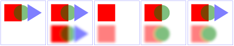
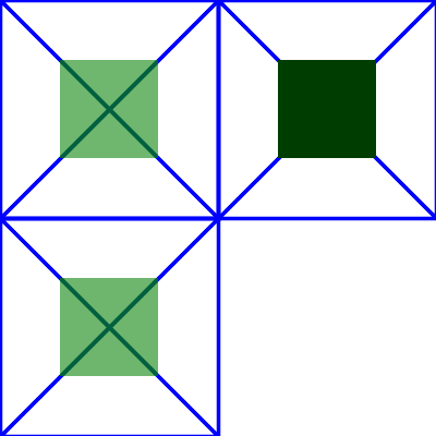
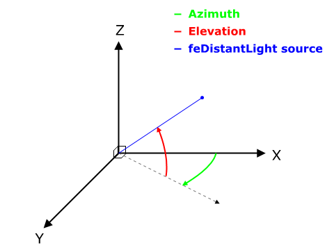
